No. 249,097 – Shave (Henry P. Roberts) (1881)
UNITED STATES PATENT OFFICE.
_________________
HENRY P. ROBERTS, OF JAMESTOWN, N. Y., ASSIGNOR OF THREE-FOURTHS TO THE HORTON MANUFACTURING COMPANY, OF SAME PLACE.
SHAVE.
_________________
SPECIFICATION forming part of Letters Patent No. 249,097, dated November 1, 1881.
Application filed June 1, 1881. (No model.)
_________________
To all whom it may concern:
Be it known that I, HENRY P. ROBERTS, a citizen of the United States, residing at Jamestown, in the county of Chautauqua and State of New York, have invented certain new and useful Improvements in Shaves; and I do hereby declare that the following is a full, clear, and exact description of the invention, which will enable others skilled in the art to which it appertains to make and use the same, reference being had to the accompanying drawings, and to the letters of reference marked thereon, which form a part of this specification.
The object of this invention is to combine a gage or friction roller with a cutting edge or blade.
The principle of my invention can be shown in a heel-shave by which any of the ordinary-shaped heels may be operated upon, the tool adjusted to cut thin shavings of leather, and the shavings moved rapidly away from the knife-edge, to prevent clogging of the shavings-passage, and the tool can also be used upon wood as an ordinary spokeshave.
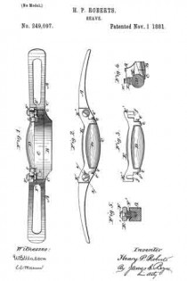
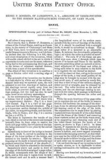
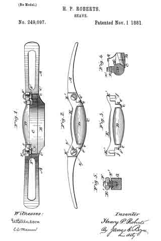
In the accompanying drawings, Figure 1 is a bottom view of a spoke or heel shave with my improvement thereon. Fig. 2 is a front view thereof. Fig. 3 is a view of the gage-roller and the frame thereof, detached. Fig. 4 is a transverse section through the middle of the roller, its supporting-frame, and the knife-blade, with its frame; and Fig. 5 is a section on line x x of Fig. 2.
The letter A represents the handle of the tool, which is curved at the center and recessed inwardly from its front edge, to receive the knife and gage-roller, the two parts of the handle being conneoted in one piece by the curved bridge B.
Immediately in front of the bridge is located the knife-blade C, curved to conform to the shape of the lower surface of the bridge, and secured to the handle by screws c. The cutting-edge of the knife is turned outwardly and projects somewhat forward of the shanks C’, by which said blade is attached to the handle.
Immediately above and partly in front of the edge of the knife is arranged a gage-roller, D, which corresponds with the shape of the knife, and in this case it tapers from its middle toward each end in such a manner that the longitudinal curve of its surface corresponds with the curve of the edge of the knife; but if it should be combined with a straight knife, it would be cylindrical in shape. This gage-roller D is mounted in an adjustable frame, E, between the downwardly-projecting lugs e, on which the roller is pivoted on screw-pivots e’. The ends E’ of the frame are provided with open slots f, through which pass screws F to secure said frame to the handle, the slots permitting either an upward or downward adjustment of the frame and roller, to bring said roller in such relation to the knife as to regulate the cut thereof as desired.
It will be observed that, owing to the curved shape of the knife, a very small portion of its edge may be brought in contact with the surface acted upon, if said surface is nearly flat, and that a heel of any of the ordinary shapes, either curved or straight, may be trimmed by the tool. The roller revolves as the tool advances, and the cut shavings coming in contact with the roller, their passage is facilitated through the opening between the roller and knife.
While the main functions of the gage-roller are to regulate the out of the knife, to remove friction and facilitate the passage of the shavings, it can be adjusted also to compensate for the wearing away of the edge of the knife. The adjustment can be made either by placing washers between the ends E’ of the roller-frame E and the frame of the blade C and removing these washers as fast as the blade wears away, or by supporting and clamping each end of the roller-frame between the heads of two screws, as shown in Figs. 1 and 5. In these figures, F’ represents the screws, inserted adjustably in the frame A. The flat head of said screws is hollow, and screw-tapped internally to receive the clamping-screws F, so that whatever may be the width of the blade C the roller D can be made to follow its edge, and the frame of said roller can be secured at each end.
I do not limit the use of my invention to heel or spoke shaves, as it is applicable to other cutting-instruments-for instance, carpenters’ planes.
Having now described my invention what I claim is —
1. The combination , with the handle, recessed as described, of the curved knife C, and the gage-roller tapered from its middle to its ends to conform to the curves of said knife, substantially as and for the purpose set forth.
2. The combination, with the recessed handle having the curved knife C secured thereto, of the roller D, arranged above said knife and mounted in an adjustable frame, E, substantially as described.
3. The combination with the handle, recessed as described, and having secured thereto the curved knife C, of the roller D, mounted in an adjustable frame, E, having the lugs e, between which the roller is pivoted, and between which the edge of the knife extends, substantially as described.
4. The combination of the centrally-curved handle, curved knife C, tapering roller D, and frame E, with adjustable hollow screws F’ and clamping-screws F, substantially as and for the purpose described.
In testimony that I claim the foregoing as my own I have hereto affixed my signature in presence of two witnesses.
HENRY P. ROBERTS.
Witnesses:
JAMES I. FOWLER,
WILLIAM K. VANDERGRIFT.

