| PLEASE NOTE: The images presented on this page are of low resolution and, as a result, will not print out very well. If you wish to have higher resolution files then you may purchase them for only $2.95 per patent by using the "Buy Now" button below. All purchases are via PayPal. These files have all been cleaned up and digitally enhanced and are therefore suitable for printing, publication or framing. Each zip package contains all the images below (some packages may contain more), and purchased files can be downloaded immediately. |
UNITED STATES PATENT OFFICE.
_________________
WILFRED R. LANSBERRY, OF DES MOINES, IOWA.
JOINING-PLANE.
_________________
890,519. Specification of Letters Patent. Patented June 9, 1908.
Application filed September 19, 1907. Serial No. 393,734.
_________________
To all whom it may concern:
Be it known that I, WILFRED R. LANSBERRY, a citizen of the United States, residing at Des Moines, in the county of Polk and State of lowa, have invented a certain new and useful Joining-Plane, of which the following is a specification.
The object of my invention is to provide a plane especially designed for use in trimming or cutting away the edge of a board on a line exactly parallel with the edge of another board placed adjacent to it, so that said boards may be fitted together accurately and smoothly, and my device is of special advantage in cases where neither of the boards to be fitted have perfectly smooth straight edges, and where it is necessary to do the work by hand.
My invention consists in the construction of the joining plane, whereby the objects contemplated are attained, as hereinafter more fully set forth, pointed out in my claims and illustrated in the accompanying drawings, in which —
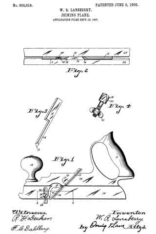
Figure 1 shows a side elevation of a joining plane embodying my invention. Fig. 2 shows an enlarged sectional view on the line 2–2 of Fig. 1, also showing two boards in position to be operated on by the plane, one of said boards formed with a cut such as would be made by the plane. Fig. 3 shows a perspective view of the plane bit detached, and Fig. 4 shows a perspective view of the bolt for clamping the bit to the plane.
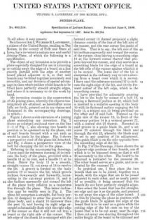
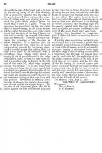
Referring to the accompanying drawings, I have used the reference numeral 10 to indicate the body of the plane, provided with a handle 11 at its rear, and a handle 12 at its front. Below the body 11 is a smooth, straight runner 13, cut away at 14 to receive the bit. A groove is formed on the body portion 10 to receive the bit, which groove inclines downwardly and forwardly, terminating in the cut-away portion 14, and it also inclines rearwardly and toward the left of the plane body relative to a transverse line through the plane. This latter inclination may be readily seen in Fig. 2. The plane bit comprises a straight, flat body portion 15 designed to enter the groove in the plane body, and a shank 16 narrower than the part 15, and having its right edge arranged substantially flush with the right edge of the runner so that it will not cut into a board at the right side of the runner. The left edge ofthe shank 16 is arranged with the forward corner 18 thereof projected a slight distance outside of the line of the left side of the runner, and the rear corner lies inside of said line. That is to say, the left side of the bit inclines rearwardly and toward the center of the runner, thus leaving a smoothing edge 18 at the forward corner thereof that projects beyond the runner, and that serves as a smoothing blade for the edge of a board at the left side of the runner against which it is to be moved. The lower end of the bit is sharpened in the ordinary way to cut a shaving from a board over which it is moved. I have used the reference numeral 17 to indicate the right edge of the bit, and 18 the forward corner of the left edge, which is the smoothing center.
I have provided for adjustably securing the bit to the body by means of a bolt 19, having a flattened portion at 20, which bolt is inserted in a suitable opening in the body 10 with its flattened surface engaging the bit body 15, a winged nut 21 being provided on the other end of said bolt. Formed on the right side of the runner 13, in front of the cut-away portion 14 is a vertical groove 22, with a central slot 23 therein. Mounted in said groove is a guide blade 24, and a set screw 25 extends through the blade and through the slot 23, whereby the blade may be set to any position of its adjustment. This guide blade is on the side opposite from the smoothing edge of the bit.
In Fig. 2 of the drawings, I h ave shown the adjacent edge portions of two boards, one of which is to be trimmed down so that it will fit accurately to the other. The board to be trimmed is indicated by the numeral 26. The other board serves as a guide, and is indicated by the numeral 27.
In practical use, I first place the two boards that are to be joined, together on a bench, with the edges that are to be joined adjacent to each other, and as nearly parallel as possible, it being assumed that the boards do not have perfectly straight edges. I then select the board that has the straightest edge and use it as the guide, and proceed to cut away the edge of the other board. I do this by placing the plane in position with the guide blade 24 against the edge of the board that is to be used as a guide while the cutting edge of the bit rests on top of the board that is to be cut away, near its edge. I then cut away one shaving throughout the entire length of the board to be trimmed and obviously the edge of the board that is formed by the cutting away of the first shaving, will be absolutely parallel with the edge of the guide board, I then continue the operation of cutting away one shaving at a time, until the guide blade projects below the board that is used as a guide. When the operation has proceeded. this far, the guide blade is not necessary, as the plane runner will be guided between the edge of the guide board and the edge of the board being cut that was formed by the removal of the shavings thus far made. Then the operator continues the removing of the shavings as before described. It is essential that the edge of the board first being cut be made comparatively smooth by the joining plane, for if it were left rough and uneven, then the edge would have to be smoothed with a smoothing plane, which might result in leaving it out of parallelism with the edge of the guide board, so that it is very essential that a smoothing edge be formed on the left side of the plane bit, which edge projects beyond the runner. It is also important that this smoothing edge be so arranged that it will not cut a shaving from the edge of the board, but it will smooth the edge by removing rough and uneven pieces left thereon by the successive cutting of shavings from said edge portion. Heretofore in dressing down the edge of a board, the plane bit has usually been placed against the edge to be cut. By the use of my improved plane, the bit is placed against the side of the board adjacent to the edge that is being trimmed, and the shavings are cut away successively until the board is entirely cut through from one side to the other. The guide board is firmly fixed in position throughout the entire operation so that when the board is cut through as before described, the resulting edge will be exactly parallel with the edge that was used as a guide, no matter how irregular the edge of the guide board may have been.
Having thus described my invention, what I claim and desire to secure by Letters Patent, is —
A joining plane comprising a straight runner formed with a bit recess, a guide blade adjustably mounted on one side of the runner in front of the bit recess, and abit adjustably mounted, having a sharpened lower edge, the front edge of the bit being inclined from a transverse line through the runner rearwardly, and to the left, the right edge of the bit being contained inside of the line of the right side of the runner, and the left edge of the bit having its forward corner projected outwardly beyond the runner to form a smoothing edge at the forward corner of said left side, and its left side inclined rearwardly and toward the center of the runner, the rear corner thereof being inside of the line of the left side of the runner.
Des Moines, Iowa, Aug. 21, 1907.
WILFRED R. LANSBERRY.
Witnesses:
RALPH ORWIG,
S. F. CHRISTY.


