| PLEASE NOTE: The images presented on this page are of low resolution and, as a result, will not print out very well. If you wish to have higher resolution files then you may purchase them for only $2.95 per patent by using the "Buy Now" button below. All purchases are via PayPal. These files have all been cleaned up and digitally enhanced and are therefore suitable for printing, publication or framing. Each zip package contains all the images below (some packages may contain more), and purchased files can be downloaded immediately. |
UNITED STATES PATENT OFFICE.
_________________
ANDRO NYLUND, OF DULUTH, MINNESOTA.
PLANE.
_________________
879,793. Specification of Letters Patent. Patented Feb. 18, 1908.
Application filed May 28, 1907. Serial No. 376,047.
_________________
To all whom it may concern:
Be it known that I, ANDRO NYLUND, a citizen of the United States, and a resident of Duluth, in the county of St. Louis and State of Minnesota, have invented a new and Improved Plane, of which the following is a full, clear, and exact description.
This invention relates to planes, and it is particularly useful with rabbet or dado planes.
The object of the invention is to provide a simple, strong and efficient plane, having adjustable means for limiting the depth to which the cut of the plane may proceed, and which is provided with means for easily adjusting the plane iron and for locking the same in position.
A further object of the invention is to provide a plane having guide blades at both sides thereof, which can be easily and quickly adjusted, and which has means for limiting the projection of the blades.
The invention consists in the construction and combination of parts to be more particularly described hereinafter and fully set forth in the claims.
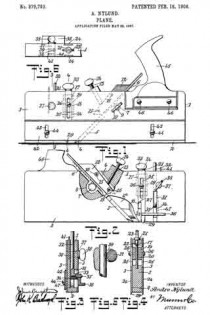
Reference is to be had to the accompanying drawings forming a part of this specification, in which similar characters of reference indicate corresponding parts in all the views, and in which Figure 1 is a side elevation of the plane; Fig. 2 is an elevation of the opposite side of the plane, showing parts broken away and in section 5 Fig. 3 is a vertical cross-section on the line 3–3 of Fig. 1; Fig. 4 is a vertical cross-section on the line 4–4 of Fig. 1; Fig. 5 is an enlarged view of a detail showing parts in cross section and parts broken away; and Fig. 6 is a plan view of a part of the plane.
Referring more particularly to the drawings, 1 represents the body of the plane, which may be of wood or any other suitable material. Secured to the body 1 is the sole-plate 2 extending the entire length of the tool. Side-plates 3 are secured to the sides of the body, and like the sole-plate 2 may be of steel or any other suitable material, preferably metal. The body 1 is cut away between the sides to form a plane iron recess 4. The recess 4 presents a flared opening 4a at the side, through which the shaving formed by the plane iron can leave the tool. The plane iron 5 is mounted in the recess 4 and presents a rack 6. A pinion 7 in mesh with the rack 6 is rotatably mounted in an extension 8 of the recess 4. The pinion 7 has a shank 9 extending through the side of the plate and provided with a wing 10, by means of which it may be operated. A locking-block 12 is secured upon the plane iron on the side opposite to the pinion 7. A set-screw 13 is mounted in a suitably threaded opening of the body and abuts against the block 12. The set-screw 13 is provided with a- wing 14 by means of which it may be operated to jam the plane iron in position through the block 12, which is carried in the recess 4 upon transverse pins 15 arranged in openings 16 of the block.
A recess 17 is formed in the body between the side plates 3, and connects with lateral guide grooves 18 formed at the sides of the body by the side-plates 3 which are cut away for this purpose. A threaded member 19 is arranged slidably in the recess 17 and is engaged by a screw pin 20. The screw pin 20 has a collar 21 seating against the upper part of the body, and a nut 22 in engagement with the inner wall of the recess to prevent the displacement of the screw pin, which has at its outer extremity a wing 23 by means of which it may be manually operated to adjust the member 19 within the recess. It will be understood that as the screw pin 20 is turned the member will move up or down within the recess. Guide blades 24 are slidably mounted in the guide grooves 18 and have slots 25. The guide blades 24 are adjustably secured to the member 19 by means of screws 26 arranged in the slots 25 and secured in suitable threaded openings in the member 19. The guide blades 24 have shoulders 27 adapted to engage with shoulders 28 formed at an edge of each slot, to limit the projection of the cutting point 29 of the blade from the groove. The guide blades are adapted to be projected a distance beyond the sole of the plane, equal at least to the projection of the plane eyes. In the operation of the plane in the usual manner, the guide blades form parallel grooves or guides exactly within and between which the plane iron follows and cuts the shaving.
A vertical guide-way 30 is formed within the body and has a lateral slot 31 extending through the side 3. A slidable member 32 comprising substantially a rod, is arranged within the guide-way 30 and has a lateral extension 33 in the slot 31. A gage member is secured to the extension 33 by means of a screw 35. The gage member 34 has a supplemental sole 36. The gage member may be adjusted at the side of the body by moving the member 32 up or down within the guide-way. A transverse pin 37 is arranged adjacent to the member 32 and has a wing 33 at the side, by means of which it may be operated. An eccentric cam groove 39 is formed in the pin 37. When the member 32 engages the cam groove at the greatest depth of the same the member is free to slide within the guide-way. When the pin 37 is rotated from this position the member 32 is jammed within the guide-way by the cam-like action of the groove. The pin 37 is provided with a second annular groove 40 with which a pin 41 carried by the body engages to prevent the lateral displacement of the adjusting pin 37. Aleaf spring 47 is arranged in the guide-way 30 and engages the member 32 to hold the same resiliently within the guide-way and to prevent lateral movement of the same. The gage 34 serves to determine and measure the depth oi the rabbet formed by the plane. A guide-plate 42 having slots 43 is adjustably mounted at the side of the plane opposite to the gage 34, by means of set-screws 44 arranged in the slots 43 and in suitable openings of the body. The guide-plate 42 extends the entire length of the plane and is adapted to be projected below the sole of the same to guide the tool at the edge of the work when a rabbet is being cut. A handle 45 is mounted by means of screws 46 at one side of the plane and serves for holding the tool when it is in operation.
Having thus described my invention I claim as new, and desire to secure by Letters Patent:
1. In a plane, a plane iron having a rack, and a pinion adapted to be manually controlled and operatively engaging with said rack, a block tapered toward the cutting edge of said iron and loosely mounted to engage the same, and a set screw adjustably engaging said block to lock said iron in position.
2. In a plane, a body having a guide-groove, a guide-blade mounted to slide in said groove, a movable member arranged to slide in the longitudinal direction of said groove and having an adjustable connection with said blade, and means for adjusting said member.
3. In a plane, a body having a recess, and a guide-groove communicating with said recess, a movable member in said recess, a guide-blade in said groove and having an adjustable connection with said member, and a screw-pin engaging with said member and controlling the same.
4. In a plane, a body having a recess, and a guide-groove communicating with said recess and presenting a shoulder, a movable member in said recess, a guide-blade in said groove and having an adjustable connection with said member, said guide-blade presenting a shoulder adapted to engage said shoulder of said guide-groove to limit the projection of said blade from said groove, and a screw-pin engaging with said member and controlling the same.
5. In a plane, a body having a recess and guide-grooves at opposite sides of said body and communicating with said recess, a movable member in said recess, guide-blades in said grooves and presenting slots, adjustable screws carried by said member and engaging said slots to secure said blades to said member, and a screw-pin operatively engaging said member and having collars engaging said body to prevent the longitudinal movement of said pin.
In testimony whereof I have signed my name to this specification in the presence of two subscribing witnesses.
ANDRO NYLUND.
Witnesses:
S. C. MILLER,
W. A. ANDERSON.


