No. 510,096 – Bench-Plane (Jacob Siegley) (1893)


UNITED STATES PATENT OFFICE.
_________________
JACOB SIEGLEY, OF WILKES-BARRÉ, PENNSYLVANIA.
BENCH-PLANE.
_________________
SPECIFICATION forming part of Letters Patent No. 510,096, dated December 5, 1893.
Application filed May 21, 1892. Serial No. 433,924. (No model.)
_________________
To all whom it may concern:
Be it known that I, JACOB SIEGLEY, a citizen of the United States, and a resident of Wilkes-Barré, in the county of Luzerne and State of Pennsylvania, have invented certain new and useful Improvements in Bench-Planes, of which the following is a specification.
This invention relates to certain improvements in bench-planes, and the same consists of a cast-iron bottom and steel side-plates riveted to lugs of said bottom, and of a cap that is provided with a shoulder having set-screws, said shoulder resting on a transverse rod extending between the sides of the supporting frame and screws in said shoulder permitting the adjustment of the cap into higher or lower position, all of which will be fully described hereinafter and finally pointed out in the claims.
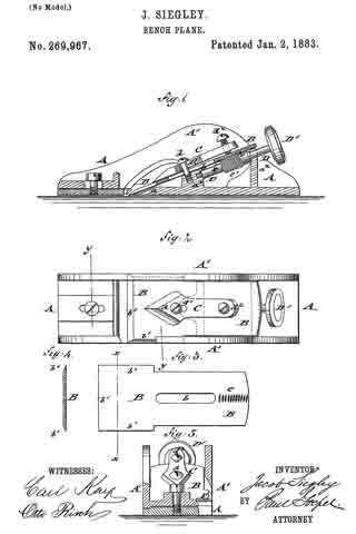
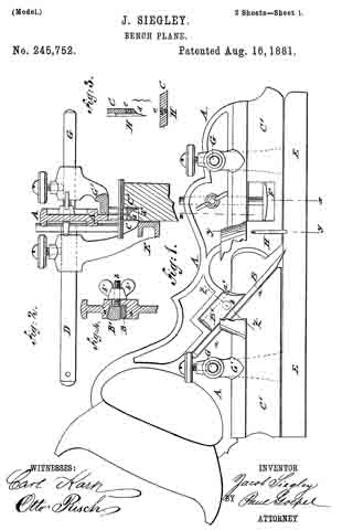
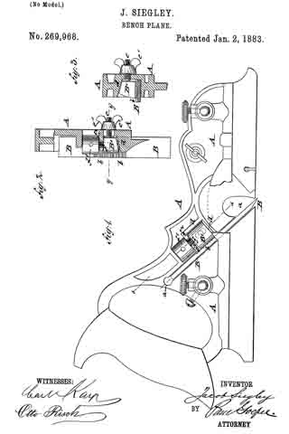
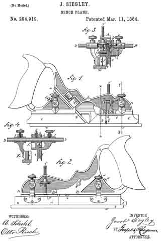
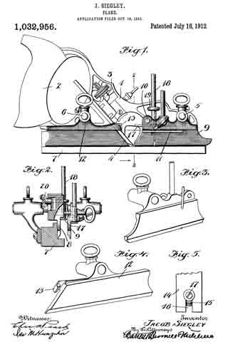
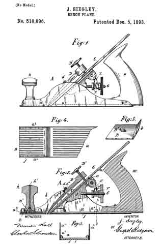
In the accompanying drawings, Figure 1 represents a side elevation of my improved bench-plane. Fig. 2 is a vertical longitudinal section of the same. Fig. 3 is a detail vertical transverse section on line 3 3, Fig. 2.
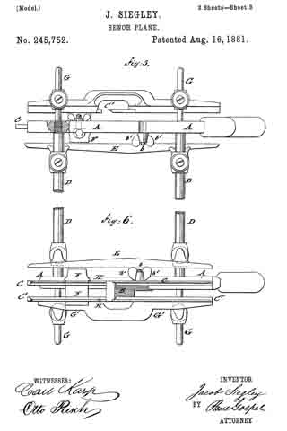
Fig. 4 is a bottom view of the front part of my improved bench-plane, and Fig. 5 is a perspective view of the throat-piece as detached from the plane.
Similar letters of reference indicate corresponding parts.
Referring to the drawings, A represents the frame of my improved bench-plane, which is composed of a cast-iron bottom plate a, provided with lugs a’ that are cast integral therewith, and of upright steel side plates a2 which are attached by rivets that are inserted into the lugs or bosses a’, as shown clearly in Fig. 3. By making the sides of steel plates a much lighter and more durable frame for bench-planes is obtained. To the rear part of the bottom plate a is attached the main handle H, while the knob h at the front end of the plane is provided with a spindle h’ having a threaded lower end that takes into an interiorly-threaded boss B’ of a detachable throat-piece B which is supported against the underside by the front part a3 of the bottom of the frame A, said bottom being a short distance from the lower edge of the frame, so as to provide for the throat piece B and bring the under side of the same accurately at a level with the under side of the main part of the bottom plate a, as shown in Fig. 2. The throat piece can be adjusted toward the blade C and cap D of the latter, as the boss of the same permits the shifting action to a certain extent in the opening of the front part a3 of the bottom plate, the knob h with its spindle h’ serving to tightly retain the throat piece on the front part of of the bottom plate. The rear end of the throat piece is provided with an upwardly inclined flange b, along which the shavings pass, as they are out off by the edge of the blade, the said flange guiding the shavings and preventing them from curling in passing up through the throat of the plane. The cap D is made tapering at its lower end, so as to bear on the blade C, while the upper end is provided with a screw D’ by which the blade C is rigidly held in position in the stock of the plane. The under side of the blade is provided with transverse grooves m, that are engaged by the tooth e of a fulcrumed arm E, the forked lower end E’ of which is engaged by a collared sleeve F that is adjustable on a fixed screw G on the fixed block J of the frame A so as to adjust thereby the blade in the stock. The cap D is provided with shoulder d which rests against the transverse rod d’ that connects the upper part of the steel side plates a2, as shown in Fig. 2, said shoulder being provided with set-screws d2 the lower ends of which bear against the transverse rod d’ said set-screws serving for raising or lowering the cap, so as to adjust it accurately in its relative position to the blade. The under side of the main part of the bottom plate a and the under side of the throat piece B are provided with longitudinal corrugations f by which the friction of the bottom of the plane with the surface to be planed is considerably reduced and an easier working than with the solid smooth bottom produced.
The bench-plane described is light and durable and the shavings are not curled in passing through the throat of the plane. The bottom corrugations facilitate the working of the plane, while the cap can be adjusted into higher or lower position, so that it is readily adjusted into its proper relative position to the plane, even as the cutting edge of the same is ground off by use.
Having thus described my invention, what I claim as new, and desire to secure by Letters Patent, is —
l. A bench-plane, the frame or stock of which is formed of a cast-iron bottom having bosses or lugs, upright steel side plates and rivets for attaching said side plates to the bosses of the bottom, substantially as set forth.
2. The combination, with the stock of a bench-plane having a fixed transverse rod, of a blade, a cap supported on said blade, said cap being provided with a shoulder above the transverse rod and set screws passing through said shoulder so as to permit the adjustment of the cap relatively to the blade, substantially as set forth.
In testimony that I claim the foregoing as my invention I have signed my name in presence of two subscribing witnesses.
JACOB SIEGLEY.
Witnesses:
JOHN A. SAYER,
J. G. KAUFER.