
| PLEASE NOTE: The images presented on this page are of low resolution and, as a result, will not print out very well. If you wish to have higher resolution files then you may purchase them for only $2.95 per patent by using the "Buy Now" button below. All purchases are via PayPal. These files have all been cleaned up and digitally enhanced and are therefore suitable for printing, publication or framing. Each zip package contains all the images below (some packages may contain more), and purchased files can be downloaded immediately. |
UNITED STATES PATENT OFFICE.
_________________
JACOB SIEGLEY, OF NEW YORK, N. Y.
BENCH-PLANE.
_________________
Specification forming part of Letters Patent No. 245,752, dated August 16, 1881.
Application filed September 4, 1880. (Model.)
_________________
To all whom it may concern:
Be it known that I, JACOB SIEGLEY, of the city, county, and State of New York, have invented certain new and useful Improvements in Bench-Planes, of which the following is a specification.
This invention relates to improvements in the benchplane for carpenters’ use for which Letters Patent have been granted to me heretofore, under date of July 1, 1879, and numbered 216,979, the improvements being designed for the purpose of simplifying the construction and render the plane more convenient in use and less expensive.
The invention consists of a bench-plane the stock of which is provided with a fixed blade having a concave taper at its lower part, in combination with an auxiliary and laterally-adjustable blade having a similar taper symmetrically to that of the blade of the stock.
The invention consists, secondly, of a stock; which is provided at one side with detachable guide arms or posts tor the laterally-adjustable side gage or fence, and with shorter arms or guide-posts at the opposite side for the auxiliary blade. The plow or other cutting-tool is secured to the inclined bearing-surface of the stock by a wedge-piece and clamping-screw, the wedge-piece being guided along a flared cheek of the stock.
The invention consists, lastly, of the fastening of the advance cutters into grooves of the blades by clamping-screws flush with the blades.
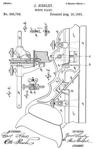
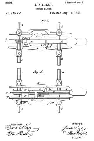
In the accompanying drawings, which illustrate iny invention, Figure 1 represents a side elevation of my improved bench-plane ; Fig. 2, a vertical transverse section of the same on line x x, Fig. 1; and Figs. 3 and 4 are detail vertical transverse sections, respectively on lines y y and z z, Fig. 1, showing the fastening of the advance cutters to the blades of the plane and the locking wedge-piece of the plow or rabbeting-cutters. Figs. 5 and 6 are respectively a top view, partly in section, and a bottom view, of my bench-plane.
Similar letters of reference indicate corresponding parts.
In the drawings, A represents the stock of my improved bench-plane, which is made of iron or other suitable metal, with the customary handle at one end and an inclined bearing-surface, a, for the detachable plow or other cutting-tool B at the middle portion thereof. The plow B is secured to the bearing-surface by means of a sliding wedge-piece, B’, which is guided along a flared cheek, a’, of the stock A by means of a screw-post, b, secured to the wedgepiece, and a clamping-nut, b’, as shown, respectively, in Figs. 1 and 4.
The stock A is provided at its lower part with a fixed blade, C, which extends throughout the whole length of the stock, and is provided at one side thereof with a concave taper, d, as shown clearly in Fig. 2.
Horizontal guideposts D extend at one side from the stock and are screwed in detachable manner into sockets of the stock, and provided at the outer ends with diametrical holes for more easily detaching them from the stock. On the guide-posts D is supported the laterally-adjustable gage or fence E, which is secured in the usual manner to the post by set-screws. This gage orfence E serves to guide the plane when it is used as a plow, bead, or rabbeting plane, at the required distance from the edge, in the well-known manner in planes. The stock A is next provided, in front ofthe plow, with a stop-gage, F, which extends sidewise at both sides of the blade and is vertically adjustable in a recess of the blade, and secured at the proper height by a side clamp-screw, as shown in Fig. 1. The stock is furthermore provided, at the side opposite to that to which the guide-posts D ofthe fence E are applied, with fixed horizontal guide-posts G, which serve for the support of an auxiliary blade, C’ The blade C’ is attached to the lower ends of arms G’, the upper sleeve -shaped ends of which are guided on the posts G and secured thereto by set-screws. This auxiliary blade C’ is provided at its inner side, facing the blade of the stock A, with a concave taper, d’, which is symmetrical to that of blade C.
The auxiliary blade C’ is adjusted laterally on its guide-post for plows or cutters of different sizes, the concave edges of both blades C and C’ serving for guiding the plane along the bead formed by the bead-cutters. The tapering edges d d’ have but a small degree of concavity, so as to be adapted for use with the different sizes of bead-cutters.
The blades C and C’ are arranged between the plow or rabbeting-cutter and the stop-gage F, with advance cutters H, which are shown in Figs. 1 and 3. These advance cutters H are inserted into side grooves of the blades C and C’, which grooves encircle nearly entirely the advance cutters, so that they may be firmly forced by fastening clamp-screws e against the approaching edges ofthe grooves and thereby securely held in position. The cutting-edges of the advance cutters H are thereby in line with the outer surface of the blades C C’, which is essential for the proper action of the advance cutters. The advance cutters serve for all sizes of plows and cutting-irons and dispense with running a gage over the board and prevent the plows from tearing the edges in cross-grained timber.
When the advance cutters are worn out their fastening-screws are loosened and the cutters adjusted by being pushed downward in their guide-grooves and then reclamped by the fastening-screws, the heads of which are preferably flush with the blades. The advance cutters are made of the best steel, sharpened from time to time, and replaced by new cutters when worn out.
By means of the laterally-adjustable auxiliary blade and interchangeable ploivs and cutters the improved bench-plane may be used for grooving, beading, and rabbeting, either as a plow, bead-plane, scratch-bead, match-plane, and dado or rabbeting-plane. When used as a dado the fence and its guide-posts are detached, so as not to interfere with the hand in holding the square. It may be also used by the carpenter for sash-moldings and for other purposes, as it combines a number of useful features in a very compact and durable manner.
Having thus described my invention, I claim as new and desire to secure by Letters Patent —
1. In a bench-plane, the stock with fixed blade G and laterally-adjustable auxiliary blade C’, having concave tapers d’ on their inner sides, and an inclined bearing-surface, a, in combination with the holding device, as shown in Figs. 1 and 4, substantially as set forth.
2. In a bench-plane, the combination of the blades C C’, the side grooves therein, the arms G’, the advance cutters H, the stop-gage F, the guide-post D, and the fence E, substantially as set forth.
3. In a bench-plane, the stock having an inclined bearing-face, a, and a recess with a flaring cheek, a’ a, plow B, a sliding wedge-piece, B’, fixed screw-posts D, and clamping-nut b’, in combination with the fixed and adjustable blades C C’ and advance-cutters H, substantially as set forth.
4. In a bench-plane, the combination of the fixed and adjustable blades C C’, each having a vertical and nearly circular side groove or socket, with advance cutters H and clamp-
screws e, bearing on their inner sides, the advance cutters being, on the outer side, flush with the outer surface of the blades, substantially as set forth.
In testimony that 1 claim the foregoing as my invention I have signed my name, in presence of two witnesses, this 24th day of August, 1880.
JACOB SIEGLEY.
Witnesses:
PAUL GOEPEL,
CARL KARP.