| PLEASE NOTE: The images presented on this page are of low resolution and, as a result, will not print out very well. If you wish to have higher resolution files then you may purchase them for only $2.95 per patent by using the "Buy Now" button below. All purchases are via PayPal. These files have all been cleaned up and digitally enhanced and are therefore suitable for printing, publication or framing. Each zip package contains all the images below (some packages may contain more), and purchased files can be downloaded immediately. |
UNITED STATES PATENT OFFICE.
_________________
THOMAS A. MASTERS, OF BINGHAM CANYON, UTAH.
CARRIAGE-MAKER’S PLANE.
_________________
1,325,101. Specification of Letters Patent. Patented Dec. 16, 1919.
Application filed April 3, 1919. Serial No. 287,291.
_________________
To all whom it may concern:
Be it known that I, THOMAS A. MASTERS, a citizen of the United States, residing at Bingham Canyon, in the county of Salt Lake and State of Utah, have invented certain new and useful Improvements in Carriage-Makers’ Planes, of which the following is a specification.
My invention relates to planes, and has particular reference to improvements in a carriage maker’s rabbet plane.
An important object of the invention is to provide means for preventing the shavings from sticking within the mouth of the plane, and clogging the same, such means being adapted to either raise the shavings and facilitate their discharge from the machine or cut or break the shavings thereby rendering them easy to discharge.
A further object of the invention is to provide a device of the above-mentioned character, which is simple in construction, cheap to manufacture and convenient to use.
Other objects and advantages of the invention will be apparent during the course of the following description.
In the accompanying drawings forming a part of this specification and in which like numerals are employed to designate like parts throughout the same;
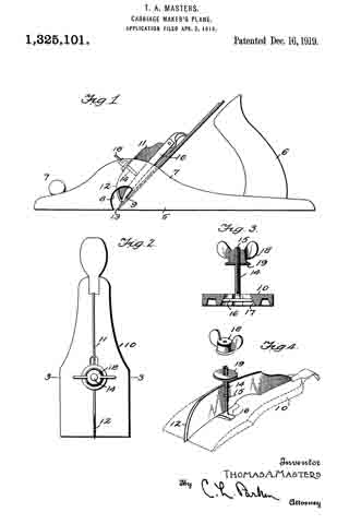
Figure 1 is a side elevation of a plane having my device applied thereto;
Fig. 2 is a side elevation of the clamping plate, having my attachment applied thereto;
Fig. 3 is a transverse sectional view, taken on line 3–3 of Fig. 2; and Fig. a is a perspective view of the attachment embodying my invention, parts being separated.
In the drawings, wherein for the purpose of illustration is shown a preferred embodiment of my invention, the numeral 5 designates the stock or body portion of a carriage maker’s rabbet plane, having the usual handle 6, secured to the rear end thereof, and knob 7 to the forward end. The stock 5 includes upstanding sides or flanges 7. Formed through the stock 5 is a transverse mouth 8, extending through the lower edge of the stock and through the opposite sides thereof. The numeral 9 designates the cutter blade of the plane, which extends for substantially the entire width of the stock 5 and mouth 8, thereby causing the shavings to stick within the mouth clogging the plane. The numeral 10 designates the usual clamping or adjusting plate carried by the stock 7 for locking the blade 9 in adjustment at the desired position.
My attachment comprises a blade 11, arranged upon edge and contacting with the plate 10. The blade 11 extends longitudinally of the plate 10 and has its lower end tapered, the same being provided with a rounded cutting edge 12. The lower end of the plate 10 projects into the mouth 8 and is positioned near the cutting edge 13 of the blade 9. The blade 11 is held in place by means of a bolt 14, having a longitudinal slot 15 receiving the blade 11. At its inner end the bolt 14 has a transverse head 16, held within a recess 17 formed upon the lower side of the plate 10. The upper end of the bolt 14 is screw threaded to receive a winged nut 18, contacting with a washer 19 arranged to engage the blade 11. By this means the blade 11 may be securely locked in place in clamping engagement with the plate 10.
The plane is used in the ordinary manner, and the shavings pass into the mouth 8, contact with the blade 11, and may be raised, thereby facilitating their discharge from the plane. The shavings which are not thus raised are split or broken up by the blade 11, whereby they freely discharge from the plane.
It is to be understood that the form of my invention herewith shown and described is to be taken as the preferred example of the same, and that various changes in the shape, size, and arrangement of parts may be resorted to without departing from the spirit of my invention or the scope of the subjoined claims.
Having thus described my invention, I claim :–
1. The combination with a bench plane, of a thin blade arranged transversely to and intermediate the width of the plane-bit and having its forward end sloping upwardly and rearwardly from the plane of said bit to raise or deflect the chips, and means for detachably mounting said blade.
2. The combination with a bench plane-bit, a thin blade arranged transversely and intermediate the width of the plane-bit, and having its forward edge sharpened to split the chip, and means for detachably mounting said blade.
3. The combination with the bench plane bit, of a thin blade arranged traversely of and intermediate the width of said bit, and having its forward edge sloped upwardly and rearwardly from the front of said bit, and sharpened to raise or deflect and split the chip and means for detachably securing the blade to the said bit.
In testimony whereof I affix my signature in presence of two wltnesses.
THOMAS A. MASTERS.
Witnesses:
J. L. HUCHEL, D. D. S.,
JESS. ZABRISPIE.


