| PLEASE NOTE: The images presented on this page are of low resolution and, as a result, will not print out very well. If you wish to have higher resolution files then you may purchase them for only $2.95 per patent by using the "Buy Now" button below. All purchases are via PayPal. These files have all been cleaned up and digitally enhanced and are therefore suitable for printing, publication or framing. Each zip package contains all the images below (some packages may contain more), and purchased files can be downloaded immediately. |
UNITED STATES PATENT OFFICE.
_________________
EDMUND A. SCHADE, OF NEW BRITAIN, CONNECTICUT, ASSIGNOR TO THE STANLEY RULE &
LEVEL COMPANY, OF NEW BRITAIN, CONNECTICUT, A CORPORATION OF CONNECTICUT.
CARPENTER’ S PLANE.
_________________
1,331,280. Specification of Letters Patent. Patented Feb. 17, 1920.
Application filed November 6, 1919. Serial No. 336,122.
_________________
To all whom it may concern:
Be it known that I, EDMUND A. SCHADE, a citizen of the United States of America, residing at New Britain, Connecticut, have invented new and useful Carpenters’ Planes, of which the following is a specification.
The main object of my invention is to provide a simple, rigid construction in which the blade is so supported that it may be readily adjusted to vary the cutting depth and yet so that the blade may be readily removed and replaced in its proper position without changing the adjustment. Another object is to maintain the parallelism of the cutting edge of the cutter when adjusting the depth of cut.
In its preferred form the body of the plane is of metal and provided with a guide frame rigidly secured to the body. The cutter is provided with a detachable clamp block by means of which it is guided in the frame. The adjustment is effected by a screw coacting with the guide frame and the clamp block. A cap member holds the cutter in position.
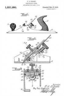
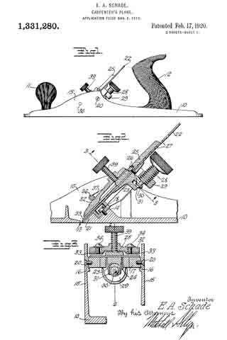
Figure 1, is a side view of a plane embodying the improvements of my invention.
Fig. 2, is a longitudinal sectional view on the plane of the line 2–2 of Fig. 3 on a larger scale than Fig. 1.
Fig. 3, is a transverse sectional view on the plane of the line 3–3 of Fig. 2.
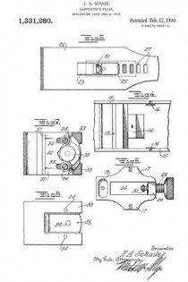
Fig. 4, is a fragmentary plan view of the parts of the body of the plane embodying my improvements.
Fig. 5, is a detail plan view of the guide frame, detached.
Fig. 6, is a detail view showing the underside of the cutter and the clamp block.
Fig. 7, is a plan view of a cap member.
Fig. 8, is a bottom view of the cap member.
The body 10 of the plane is preferably of metal and in the form shown is provided with a front handle 11 and a rear handle 12. Just in rear of the slot or throat 13, is located an inclined seat 14 between the side flanges 15, 15. Above and to the rear of this seat are seats 16, 16. On these seats 14 and 16 is mounted the guide frame 17, the lower end of which rests on the seat 14 by which it is secured for instance, by means of a screw 18, the head of which is in the recess 19. The sides of this frame 17 are secured to the seats 16, 16 of the body by suitable rivets or screws such as 20, 20, so that the guide frame 17 is rigidly held in place braced between the seat 14 above the sole of the plane and the side flanges 15, 15. Below the guide frame the plane is provided with an inclined seat 21 which forms a continuation of the inclined upper face of the guide frame 17 for supporting the cutter 22.
Attached to the cutter is a block 23 adapted to slide up and down in the opening 24 in the guide frame 17. This block is secured to the cutter by means of an upper piece 25 and the screw 26 which passes through one of the slots such as 27 in the cutter. A thumbscrew 28 which has a threaded engagement with a lug 29 of the guide frame 17 has a grooved tip 30 which engages a forked part 31 on the block 23, so that by rotating the thumbscrew 28 the block 23 and cutter 22 may be adjusted up and down on the inclined seat formed by the guide frame 17 and the part 21 of the body of the plane.
The detachable cap is made up of the two parts 32 and 33 held together by screws such as 34 passing through the slots such as 35. A cross rod 36 connects the two sides of the plane just above the cutter and spaced apart from it sufliciently to permit of introduction of the cap member. The cap member is provided with a shoulder 37 adapted to limit the downward movement of the cap member. The under side of the cap member is recessed at 38 to allow for the clamp piece 25. A thumb screw 39 is adjustable through the cap member for clamping the parts tightly in place.
To remove the cutter it is simply necessary to retract the screw 39, lift out the cap member, whereupon the cutter and the block 23 may be lifted out without affecting the adjustment of the screw 28. To replace the cutter is simply necessary to insert its lower end below the cross rod 36 and drop the forked part 31 of the block 23 over the lower end of the adjusting screw 28, which brings the cutter into exactly the same position which it was before.
It is to be noted that the guide frame which carries the adjusting screw 28 is supported from the sole and side flanges by means of three securing elements 18, 20, 20 thus giving a rigid three point support and insuring against danger of the parts becoming displaced either accidentally or through wear. These seats being relatively small and projecting from the adjacent metal of the body can be readily and accurately finished.
I claim :–
1. A plane comprising a body having a sole and side flanges, a guide frame fitted between said flanges, means passing through said frame at the lower end rigidly securing said frame to said sole, and means passing through said flanges and into said frame for rigidly securing the upper part of said frame to said flanges.
2. A plane comprising a sole and side flanges projecting upwardly from the sole, a guide frame secured near one end to said sole and at another portion to one side flange.
3. In a plane having a sole and side flanges projecting upwardly from said sole, a guide frame secured to said sole and to the side flanges for securing a rigid three point support for the guide frame in the plane body.
4. ln a plane having a sole and side flanges projecting upwardly from said sole, a guide frame between said side flanges, and means passing through said side flanges and into said guide frame for securing the latter in place.
EDMUND A. SCHADE.

