
| PLEASE NOTE: The images presented on this page are of low resolution and, as a result, will not print out very well. If you wish to have higher resolution files then you may purchase them for only $2.95 per patent by using the "Buy Now" button below. All purchases are via PayPal. These files have all been cleaned up and digitally enhanced and are therefore suitable for printing, publication or framing. Each zip package contains all the images below (some packages may contain more), and purchased files can be downloaded immediately. |
UNITED STATES PATENT OFFICE.
_________________
WILLIAM TIDGETWELL, OF MIDDLETOWN, ASSIGNOR TO THE MERIDEN MALLEABLE IRON COMPANY, OF MERIDEN, CONNECTICUT.
PLANE.
_________________
SPECIFICATION forming part of Letters Patent No. 312,229, dated February 10, 1885.
Application filed December 26, 1884. (No model.)
_________________
To all whom it may concern:
Be it known that I, WILLIAM TIDGEWELL, of Middletown, in the county of Middlesex and State of Connecticut, have invented a new Improvement in Planes; and I do hereby declare the following, when taken in connection with accompanying drawings and the letters of reference marked thereon, to be a full, clear, and exact description of the same, and which said drawings constitute part of this specification, and represent, in —
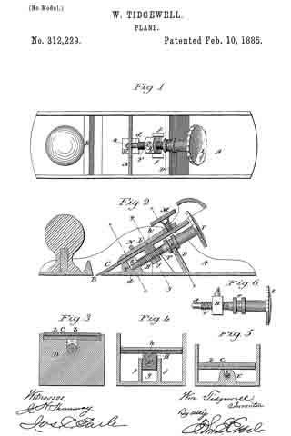
Figure 1, a top view with the cutter and its clamp removed; Fig. 2, a longitudinal central section showing the cutter in place; Fig.
3, a transverse section on line x x of Fig. 2; Fig. 4, a transverse section on line y y of Fig. 2; Fig.
5, a transverse section on line z z of Fig. 2; Fig. 6, a side view of the screw and nut detached from the stock.
This invention relates to an improvement in that class of planes for joiners’ use in which the stock is made from metal, and to which an adjusting-screw is applied to set the cutter, the object of the invention being such a construction of the stock and arrangement of the adjusting-screw that the stock may be cast complete and avoid the mechanical labor usually required in fitting the stock for the adjusting-screw, and it consists in a cast-metal stock constructed with a bearing for the cutter in rear of the mouth, the said bearing constructed with a central recess opening upward to form one seat for the screw, the second seat for the point of the screw being between said bearing and the mouth, with vertical guides for the nut between the two seats of the screw, combined with the screw and nut arranged in said seats, as more fully hereinafter described.
A represents the stock, which in general out line may be of common or usual construction; B, the bolt, through which the edge of the cutter C extends in the usual manner. At the rear a bearing, D, is arranged, upon which the cutter will rest at that point, the cutter resting at the month and upon the bearing D. This bearing D should extend across the stock between the sides, as indicated in Figs.1 and 3. Near the mouth, upon the inside and centrally between the two sides, a lug or upward projection, E, is formed, having a recess, a, from its upper edge downward. In the same central line a recess, b, is made in the bearing D.
F is the screw, its lower or point end, d, constructed to fit into the recess a in the lug E. At a point on the body of the screw corresponding to the recess b in the bearing D an annular groove, e, is formed, and so that the screw may be set, its point into the recess a and the annular groove e into the recess b, the sides of the groove taking a bearing upon the rear and front side of the bearing D, the said bearing D standing inclined at right angles to the plane of the cutter, and the axis of the screw is parallel with the plane of the cutter, as seen in Fig. 2. Midway between the bearing D and the lug E a pair of guides, f f, are arranged, one each side the screw, leaving a space, g, between them, as seen in Fig. 4.
H is the nut, threaded corresponding to the screw, and in width so as to stand between the two guides f f, as seen in Figs. 1 and 4. These guides prevent the nut from turning as the screw is turned; hence, as the screw is turned, it being fixed as to longitudinal movement, a corresponding advance or retreating movement will be imparted to the nut, and in such movement the nut is controlled by the guides f f. The screw is provided with a convenient head, I, by which it may be turned. The nut has a stud, h, projecting from its upper end, to enter a corresponding hole in the cutter, and so that the cutter will partake of the movement of the nut. As here represented, the cutter is held by a clamp, L, taking a bearing at its lower end upon the cutter, with an adjusting-screw, M, at its upper end to bear upon the cutter, the stock being provided with a fulcrum consisting of a cross-bar, N, over the cutter. Other clamps, however, may be applied to secure the cutter in place. By this construction the stock may be cast complete. The recess a for the point and the recess b in the bearing D for the screw are all formed in the process of casting, and so that, a pattern being made like the finished stock, no coring is necessary, as all the parts readily draw from the mold, leaving the cores fort he respective cavities. The screw with its nut is simply dropped into its seats before the cutter is applied. The construction is therefore of the simplest character, and greatly reduces the cost of the article over many of the complicated constructions, but having all the advantages of ready adjustment and firm hold of the cutter.
The bar N may be a piece of wire of suitable size and strength introduced into the mold, so that in the process of casting it will becorne a permanent and fixed part of the stock.
I claim —
1. A joiner’s-plane stock having the bearing D in rear ofthe mouth. a lug, E, between said bearing and mouth, the bearing D constructed with a recess, b, opening upward, and the lug E with a recess. a, also opening upward, the said two recesses forming seats for the screw, the guides f f between said bearing and lug, the said bearing, lug, and guides cast as an integral part of the stock, combined with the screw F, constructed with an annular groove, e, corresponding to the recess b in the bearing D, its point arranged in the open recess in the lug E, and the nut on said screw between said guides f f, the nut constructed to engage the cutter, substantially as described.
2. A joiner’s-plane stock having the bearing D in rear of the mouth, a lug, E, between said bearing and mouth, the bearing D constructed with a recess, b, opening upward, and the lug E with a recess, a, also opening upward, the said two recesses forming seats for the screw, the guides f f between said bearing and lug, the said bearing, lug, and guides cast as an integral part of the stock, and the cross-bar N made as a fixed part of the stock, with the screw F, constructed with an annular groove, e, corresponding to the recess b in the bearing D, its point arranged in the open recess in the lug E, the nut H on said screw between said guides f f, the nut constructed to engage the cutter, with the clamp L arranged beneath the bar N, to take a bearing upon the cutter below said bar, and an adjusting-screw above said bar, substantially as described.
WlLLlAM TIDGEWELL.
Witnesses:
ELI J. MERRIMAN,
H. W. HUDSON.