
No. 313,540 – Bench-Plane (Roscoe S. Sheldon) (1885)
UNITED STATES PATENT OFFICE.
_________________
ROSCOE S. SHELDON, OF NORTH GREENFIELD, WISCONSIN.
BENCH-PLANE.
_________________
SPECIFICATION forming part of Letters Patent No. 313,540, dated March 10, 1885.
Application filed June 5, 1884. (No model.)
_________________
To all whom it may concern:
Be it known that I, ROSCOE S. SHELDON, of North Greenfield, in the county of Milwaukee, and in the State of Wisconsin, have invented certain new and useful Improvements in Combined Tools for Carpenters’ Use; and I do hereby declare that the following is a full, clear, and exact description thereof.
My invention relates to combined tools for carpenters’ use; and it consists in peculiarities of construction, as will be more fully described hereinafter.
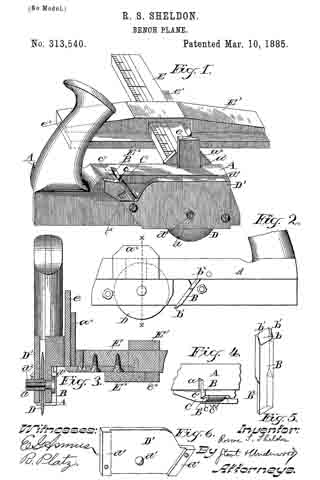
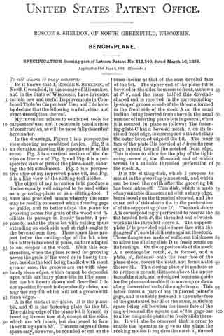
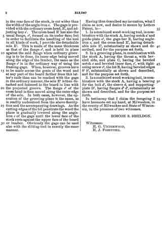
In the drawings, Figure 1 is a perspective view showing my combined device. Fig. 2 is an elevation showing the opposite side of the same. Fig. 3 is a vertical section of the device on line x x of Fig. 2; and Fig. 4 is a perspective view of part of the plane-stock, showing the bit attachment. Fig. 5 is a perspective view of my improved plane-bit, and Fig. 6 is a like view of the slitting-tool holder.
The object of my invention is to produce a device equally well adapted to be used either as a grooving-plane or as a slitting-tool. I have also provided means whereby the same may he readily connected with a framing gage or guide; and to better adapt the plane for grooving across the grain of the wood and facilitate its passage in knotty lumber, I propose to make the plane-bit with cutting-spurs extending on each side and at right angles to the beveled rear face. These spurs thus project below the cutting-edge of the bit when this latter is fastened in place, and are adapted to cut deeper in the wood. With this construction, when the plane is used for grooving across the grain of the wood or in knotty lumber, besides the tool being handled with much greater ease, the grooves are cut with absolutely clean edges, which cannot be depended upon with ordinary plane-bits in like cases; but the bit herein shown and described I do not specifically and independently claim, and may use any bit which will cut a groove with clean edges.
A is the stock of my plane. B is the plane-bit, and C is the fastening-plate for the bit. The cutting-edge of the plane-bit is formed by beveling its rear face at b, except at the sides, which are left intact, but sharpened to form the cutting-spurs b b’. The rear edges of these spurs may, however, be rounded or cut on the same incline as that of the rear beveled face of the bit. The upper end of the plane-bit is beveled on the sides from rear to front, as shown at b2 b2 and the inner half of this dovetail-shaped end is received in the correspondingly-shaped groove or side of the throat a, formed in the front side of the stock A on the usual incline, being inserted from above in the usual manner of inserting plane-bits in general, when it is secured in place as follows: The fastening-plate C has a beveled notch, c, on its inclined front edge, to correspond with and clasp the outer beveled edge of the bit. The inner face of the plate C is beveled at c’ from its rear edge inward toward the notched front edge. This is done to allow for the play of the tightening-screw c2, the threaded end of which screws in a suitable threaded perforation of the stock A.
D is the slitting-disk, which I propose to mount in the grooving-plane stock, and which can be used therewith after the grooving-bit has been taken off. This disk, which is made of any suitable diameter and with a sharp edge, bears loosely on the threaded sleeve d, and the outer end of this sleeve fits in the perforation d’ of the supporting-plate D’. The stock-fence A is correspondingly perforated to receive the flat-headed bolt d2, the threaded end of which works in the threaded sleeve d. The support-plate D’ is provided on its inner face with the flanges d3 d4, on which it rests against the stock. These flanges are made of sufficient thickness to allow the slitting-disk D to freely rotate on its bearings. On the opposite side of the stock A a rectangular notch, a’, is formed, and a plate, a2, fastened onto the rear face of the plane-stock, covers the notch and forms a slot therewith. This closing-plate a2 is made so as to project a certain distance above the upper face ofthe stock, and is designed to act as a guide for the plane and enable it to move up or down along the vertical end ofthe angle-iron e. This latter forms a part of my improved joiner’s gage, and is suitably fastened in the under face of the graduated bar E of the same, sufficient space being left between the inner face of the angle-iron and the square end of the gage-bar to allow the guide-plate at to freely slide therein. It will also be observed that in order to enable the operator to give to the plane the rocking motion it requires the notch a’, formed in the rear face of the stock, is cut wider than the width of the angle-iron e. The gage is provided with the ordinary cross-head, E’, and adjusting-key e’. The cross-head E’ has also the usual flange, e2, formed on its under face; but in order to facilitate the handling of the tool in all kinds of work, I provide the detachable sole E2. This is made of the same thickness as that of the flange e2, and is held in place against the said flange when ordinary grooving is to be done, its inner edge being moved along the edge of the lumber, the same as the flange e2 is in the ordinary way of using the framing-gage. When, however, grooves have to be made across the grain of the wood and at any part of the board farther from this latter’s ends than can be reached with the gage in the ordinary manner, the sole E2 is then detached and fastened to the board in line with the projected groove. The flange e2 of the cross-head is then moved along the outer edge of the sole. In both cases, however, the operation of the grooving-plane is the same, as is readily understood from the above description and the accompanying drawings. As the cutting-edges of the bit penetrate the wood the plane is gradually lowered along the angle-iron e of the gage until the lower face of the stock rests against the upper face of the board or lumber. Obviously the gage can be used also with the slitting-tool in exactly the same manner.
Having thus described my invention, what I claim as new, and desire to secure by Letters Patent, is —
1. In a combined wood-working tool, in combination with the stock A, having notch a’ and guide~plate a2, the gage-bar E, having angle-iron e, and the cross-head E’, having detachable sole E2, substantially as shown and described, and for the purpose set forth.
2. In a grooving-plane, in combination with the stock A, having the throat a, with beveled side, and plate C, having the beveled notch c and beveled inner face, c’, with tightening-screw c2, the bit B, having beveled edges b2 b2, substantially as shown and described, and for the purpose set forth.
3. In a combined wood-working tool, in combination with the stock A, having a bearing for the bolt d2, the sleeve d, and supporting-plate D’, having flanges d3 d4, substantially as shown and described, and for the purpose set forth.
In testimony that I claim the foregoing I have hereunto set my hand, at Milwaukee, in the county of Milwaukee and State of Wisconsin, in the presence of two witnesses.
ROSCOE S. SHELDON.
Witnesses:
H. G. UNDERWOOD,
H. J. FORSYTHE.