
No. 330,908 – Shuttle-Planer (Lodowick Leeds) (1885)
UNITED STATES PATENT OFFICE.
_________________
LODOWICK LEEDS, OF NEW LONDON, ASSIGNOR, BY MESNE ASSIGNMENTS,
TO BIRDIE L. FENNER, OF VERSAILLES, CONNECTICUT.
SHUTTLE-PLANER.
_________________
SPECIFICATION forming part of Letters Patent No. 330,908, dated November 24, 1885.
Application filed April 6, 1885. Serial No. 161,296. (No model.)
_________________
To all whom it may concern:
Be it known that I, LODOWICK LEEDS, a citizen of the United States, residing in the city and county of New London, and State of Connecticut, have invented certain new and useful Improvements in Shuttle-Planers, which improvements are fully set forth and described in the following specification, reference being had to the drawings hereunto annexed, in which —
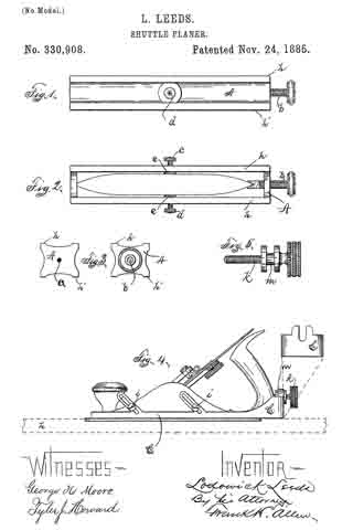
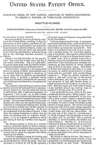
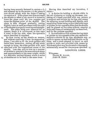
Figure 1 is a side elevation of my new device. Fig. 2 is a top or plan view, and Fig. 3 end views, of the same. Fig. 4 is a side elevation of the plane used with my shuttle-holder, and Fig. 5 a detached view of thumb-screw k.
This invention relates to a new mechanical device by means of which loom-shuttles may be securely held and planed or trued up on one or more sides, as desired, my immediate object being to produce a portable device which may be easily understood and operated, and which maybe produced at a comparatively low price.
The constant reciprocating movement of the shuttle as it travels back and forth in the shuttle-box tends to so wear the sides and bottom of said shuttle that it becomes necesssary to frequently “true it up”, or, in other words, to bring said worn bottom and sides back again to a parallel with the longitudinal center of the shuttle. The universal tendency is to wear the shuttle near each end, leaving the center somewhat full or rounded, and causing said shuttle as it travels to wabble and vibrate, instead of shooting across in a straight line. So far as I am acquainted with the state of the art, it has been the custom heretofore to either true up such worn shuttles with an ordinary bench-plane, or by an expensive machine in which the cutting is done by a swiftly-revolving cutter.
My device consists, in brief, of a metallic frame in which the shuttle is held on centers, and which is so formed that when one side of the shuttle is trued up said entire frame may be turned over to plane the opposite side before removing the shuttle.
It further consists of means for holding and squaring up said shuttle in the frame, and of an attachment by which the plane used may be raised or lowered at will by the operator, all of said improved features being described in full hereinafter.
In the accompanying drawings, A represents my shuttle-holding frame, made preferably of cast metal and in form resembling the bed of hand-lathes as commonly constructed. This frame A is drilled at one end, as at a, to provide a holding center for one of the metallic tips of the shuttle. The opposite end is drilled and tapped to receive a strong thumb-screw, b, whose inner end is cupped to provide a holding center for the other end of the shuttle, said screw b also furnishing the necessary adjustment, so that shuttles of varied lengths may be held in the same frame. Said frame is drilled and tapped on each side, at or near its center, to receive thumb-screws c d, whose inner ends are provided with loosely-fitting washers e e. When the shuttle is placed in frame A and held by its tips in the centers above described, (see Fig. 2,) the screws c d are advanced to lock said shuttle firmly in place and prevent all tendency to rock or rotate. Both the upper and lower sides of frame A are carefully planed up, forming ways or guides h h’ for the plane B to travel on.
I use preferably an iron plane of the form commonly known as the “Bailey plane,” having means for ready adjustment of the iron, and to such a plane I attach a metallic frame, C, which is so arranged that the plane may be readily lowered to reach the shuttle as said shuttle is being planed. The frame C extends along each side of the plane, being supported by screws i, which pass through diagonal slots in said frame and into the plane-frame. At the rear end of the plane is a thumb-screw, k, which is tapped into the handle or frame of the plane, and is provided with a grooved shoulder, m, which straddles the slotted rear end of frame C. (See Fig. 5.) It will now be understood that as thumb-screw k is turned to unscrew, it draws rearward with it frame C, which, owing to its diagonal bearing-slots, rises on the plane, or, if in place on the ways h, allows said plane to be slowly depressed to reach the shuttle.
My device is used as follows: The frame A is secured to a suitable bench or table, or is so placed that one end abuts against a bench-hook or other fixture on said bench, The shuttle having been securely fastened in centers a b, and squared up by the screws c d, the plane is now moved across, with the frame C resting on ways h or h’. If the plane-iron does not reach the shuttle to effect a cut, screw k is turned to lower the plane until the iron engages and trims the highest point of the shuttle. The plane is then dropped gradually, cutting slightly lower at each movement until the side of the shuttle is properly trued up and straightened. The plane being now removed for an instant, frame A is overturned, so that ways h’ come to the top side, when the operation above described is repeated.
By thus truing up the shuttle on centers, and without removing it from its supporting-frame, I am able to do the work quicker and better than heretofore, cutting off only stock enough to bring the sides parallel with each other and with the longitudinal center of the shuttle. Iam also able to true up a number of shuttles to precisely the same size and shape and approximately to the same weight, which is a desirable accomplishment where a series of shuttles are to be used in the same loom.
Having thus described my invention, I claim —
1. A device for holding a shuttle while in the act of planing or truing up the same, consisting of a frame provided with cup centers to support said shuttle by its tips, and means for squaring up and holding said shuttle, said supporting-frame being so provided with ways or guides on two opposite sides that the shuttle may be planed on two sides without removal from said frame, all substantially as described, and for the purpose specified.
2. In combination with a frame having ways or guides on two opposite sides, cup centers to support a shuttle by its tips, adjustable supports to square up and hold said shuttle on its sides, and a plane adapted to travel on said guides or ways, and provided with means by which said plane may be elevated or depressed, substantially as and for the purpose specified.
LODOWICK LEEDS.
Witnesses:
FRANK H. ALLEN,
JOHN H. KEEP.