No. 316,296 – Plane (Louis C. Rodier) (1885)
UNITED STATES PATENT OFFICE.
_________________
LOUIS C. RODIER, OF DETROIT, MICHIGAN.
PLANE.
_________________
SPECIFICATION forming part of Letters Patent No. 316,296, dated April 21, 1885.
Application filed November 8, 1884. (Model.)
_________________
To all whom it may concern:
Be it known that I, LOUIS C. RODIER, of Detroit, county of Wayne, State of Michigan, have invented a new and useful Improvement in Planes; and I do hereby declare the following to be a full, clear, and exact description of the same, such as will enable others skilled in the art to which it pertains to make and use it, reference being had to the accompanying drawings, which form a part of this specification.
My invention relates to bench-planes, and more particularly to metallic bench-planes, and has for its object, first, the combination, with a stock, of an improved knife holder or carriage provided with devices for operating the same and adjusting the knife to secure the desired depth of cut; second, the combination, with a stock, of a novel attachment for holding a toothing iron or scraper; third, to combine in a bench-plane the said knife-holder and said attachment for toothing irons and scrapers, said attachment being removable, so that the knife or bit may be removed and the toothing or scraper attachment be engaged with the stock,or said attachment be removed and the knife inserted, the plane being thus readily convertible for various uses; and, fourth, it consists in the general construction and arrangement of the novel devices, hereinafter described, and more particularly pointed out in the claims.
I carry out my invention as follows:
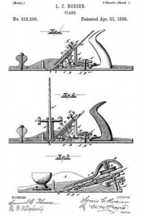
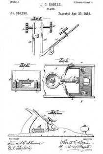
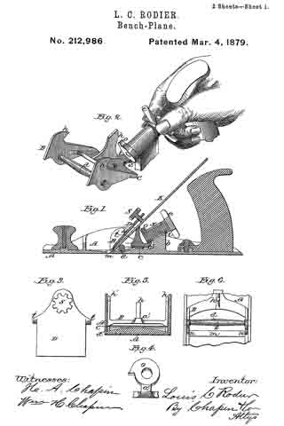
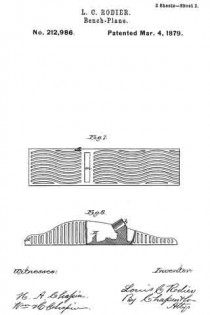
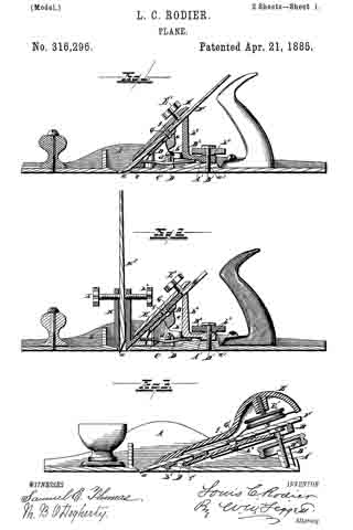
In the drawings, Figure 1 is a longitudinal section of a jack-plane, showing the knife-holder in position with the knife or bit in place. Fig. 2 is a similar section showing the toothing or scraper attachment in position. Fig. 3 is a modihcation adapting features of the device more particularly for a smoothing-plane or block-plane. Fig. 4. is a separate view of the toothing iron and scraper attachment. Fig. 5 is a cross-section along the line at x y, Fig. 6. Fig. 6 is a view showing the knife-carriage and its operating devices. Fig. 7 is a side elevation.
A represents the stock provided with a throat, a.
B is the knife-rest, which may be constructed of any suitable form or pattern, and adapted to hold the knife on a proper incline. It may be provided with ears b extending upward at the side of the knife, or these ears may be dispensed with, as shown in Fig. 3. This knife-rest is provided with a rearwardly-extending arm, b’, provided with a screw-orifice, b2, (shown in Fig. 1,) or otherwise adapted to receive the head of a screw, and to receive its force, as shown in Fig. 3. I also prefer to construct the knife-rest, when applied to jack-planes, with an extended knife-brace, b8. This knife-rest may be secured within the walls of the stock and suitably adjacent to the throat in any suitable manner, as sh own in Fig. 5. The knife-rest is screw-tapped to receive the screws b3 and b4 These screws are preferably constructed with rounded ends to engage in corresponding sockets, a’ and a2, in the base of the stock, the construction being such that the knife-rest may have a movable or slightly-vibratory movement, so that either side of said knife-rest may be elevated or depressed to more effectually adjust the knife to cut evenly across its entire edge.
C is a spring engaged with the knife-rest at one end, as shown at c, and under the arm b’
and upon a raised bed, A’, upon the base of the stock.
D is a bridging constructed preferably integral with the stock, under which the spring is extended, said bridging also preferably provided with a screw, d, adapted to bear upon the spring to give it greater tension upon the knife-rest. I do not limit myself to any special construction of this bridging.
The bed A’ is screw-tapped, as shown at a3, to receive a screw, B’.
B2 is a thumb-nut adapted to operate upon said screw, and to bear upon the rear of the arm b’ to tilt the knife-rest to any desired angle.
E is a knife-clamp provided with hooked arms e, adapted to engage over the ears b of the knife-rest, said ears being suitably cut away at their rear edge to receive said hooked arms, so that the one will be flush with the other, as shown in Fig. 7. The side walls of the stock are preferably cut away slightly to receive said ears and arms also, as shown also in Fig. 7.
E’ is a thumb-screw tapped into said clamp and adapted to tighten and hold the knife upon the knife-rest beneath. F is the knife. The clamp may have, however, any suitable engagement with the knife-rest.
When the thumb-nut B2 is forced down upon the arms b’ of the knife-rest, the effect will be to tilt the knife-rest and so adjust the knife relatively to the throat, said rest being adapted to have a slight longitudinal vibratory motion upon the ends of the screws b3 and b4, as well as a vibratory motion across the stock, while the pressure of the thumb-screw E clamps the lower part of the knife-clamp upon the knife near its cutting-edge, so that the knife is held firmly between said clamp and the knife-rest. The knife is thus readily held in position. The knife may be put in place by loosening the clamp, which is then raised to disengage its hooked arms from the ears of the knife-rest. When the knife is in place, the clamp is forced down so that its hooked arms shall be engaged over the ears of the knife-rest, and the thumb-screw may be tightened thereon when the cutting-edge of the knife has been properly adjusted.
As shown in Fig. 3, instead of providing the knife-rest with the screws b3 and b4, having rounded ends, forming the bearings of said rest, I may construct said rest with integral bearings or lugs b5, answering the same purpose as the screws in Fig. 5, the only difference being that the knife-rest cannot readily be adjusted across the stock as can be done, as already described, where the screws b3 and b4 are employed. So, also, instead of engaging the spring in the knife-rest, as shown in Figs. 1 and 2, the tension may be secured in essentially the same way by constructing the arm b with a cross-bar, as shown at b6, in which case the end of the spring may be engaged under the bridging, being passed over said cross-bar, as shown in Fig. 3, the tension being secured by means of the screw B’. By operating said screw the knife-rest may be tilted, as before, to secure the desired adjustment of the knife relative to the throat to make it cut more or less, as may desired.
To insure the proper location of the knife upon the rest and relatively to the throat, I also prefer to construct the knife with an orifice, f adapted to engage over a lug, G, which may be adjustably located beneath it either upon the spring, as shown in Fig. 3, or upon an arm, b7, integral with the knife-rest. This device when the lug is once adjusted properly will permit the ready engagement of the knife relatively to the throat, and when the knife becomes worn the lug can be adjusted to compensate for the wear.
H represents my improved toothing iron or scraper attachment, substantially as shown in Fig. 2, consisting of a suitable front clamp, H’, and rear clamp, H2, the front clamp being preferably provided with engaging-arms h, adapted to engage upon the rear clamp, said clamps provided with thumb-screws h and h2 to bind the toothing iron or scraper H3 between said clamps, as shown in Fig. 2. By means of the said screws the toothing-iron may be readily engaged in said clamps or removed thereupon for the insertion of the scraper, as desired, said clamps forming a holder or harness for the cutting-tool.
The rear clamp is provided with a wing, h3, constructed and arranged to be seated upon the knife-rest B. The knife-clamp E is then clamped upon the wing, the knife F being removed, which holds the said attachment firmly in place. It is evident that this attachment may be readily removed and the knife inserted, and vice versa.
Instead of engaging the wing h3 upon the knife-rest by means of the knife-clamp already described, the wing itself may be provided with engaging-shoulders h4, similar to the hooked arms e of said clamp, and serving a similar purpose.
I design to provide the stock of the plane with a scale-bar or measure, as shown in Fig. 7. The spring serves to take up any slack which may result in the adjustment of the knife-rest by means of the screw B’.
In the jack-plane, as shown in Figs. 1 and 2, the spring is engaged with the knife-rest forward of the bearings b3 and b4. In Fig. 3 the spring is engaged with the rest in the rear of the bearings, the spring operating simply in a reverse manner to take up the slack.
Instead of a screw, B’, a suitable cam may be employed. I would have it understood that I do not limit myself to the screw alone to secure this proper adjustment.
I do not limit myself to the definite and precise construction of the parts H’ and H2 of the attachment, as shown, nor providing the part H2 with a wing, h3, as they may be of any suitable construction to removably hold the toothing iron or scraper suitably in position in the stock.
What I claim is —
1. The combination of a plane-stock, a knife-rest provided near its lower end with a support which permits the rest to be tilted in the direction of the length of the stock and also transversely thereto, a spring to exert an upward pressure upon the rest, and means to regulate the longitudinal tilting of the rest, substantially as described.
2. The combination of a plane-stock, a knife-rest, screws passed through said rest near opposite sides thereof and bearing against said stock to permit the rest to be tilted in the direction of the length of the stock and transversely thereto, a spring to exert an upward pressure upon the rest, and means to regulate the longitudinal tilting of the rest, substantially as described.
3. The combination of a plane-stock, a knife-rest, screws passed through said rest near the opposite sides thereof and bearing against said stock to permit the rest to be tilted in the direction of the length of the stock and transversely thereto, a spring to exert an upward pressure upon the rest, means to regulate the tension of said spring, and a screw to regulate the longitudinal tilting of the rest, substantially as described.
4. The combination of the plane-stock, the knife-rest, a support under the rest, a lug, G, supported by and capable of sliding longitudinally on the support and adapted to engage and move with a knife, a knife-clamp above the rest, and a screw engaging a screw-socket in the clamp for holding the knife upon the rest, substantially as described.
5. The combination, with a metallic plane-stock, of a removable toothing iron or scraper composed of two clamps provided each with a clamping-screw, one of said clamps being provided with a wing to engage with a knife-rest on the stock, substantially as described.
6. The combination, with a plane-stock provided with a knife-rest and knife-clamp, of a removable toothing iron or scraper attachment consisting of front and rear clamps constructed and arranged to be engaged with each other and provided with clamping-screws, said rear clamp provided with a wing, h3, adapted to be engaged upon the knife-rest, the construction being such that said attachment may be removed and the knife be clamped upon the rest, and vice versa, substantially as described.
In testimony whereof I sign this specification in the presence of two witnesses.
LOUIS C. RODIER.
Witnesses:
N. S. WRIGHT,
W. B. O’DOGHERTY.

