No. 27,983 – Bench Plane (H.C. Hunt) (1860)
[paiddownloads id=”86″]27983


UNITED STATES PATENT OFFICE.

_________________

H. C. HUNT, OF OTTUMWA, IOWA.

BENCH-PLANE.

_________________

Specification of Letters Patent No. 27,983, dated April 24, 1860.

_________________

To all whom it may concern:

Be it known that I, H. C. HUNT, of Ottumwa, in the county of Wapello and State of Iowa, have invented a new and useful Improvement in Bench-Planes; and I do hereby declare that the following is a full and exact description thereof, reference being had to the accompanying drawings, which form a part of this specification.

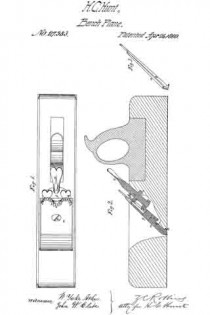
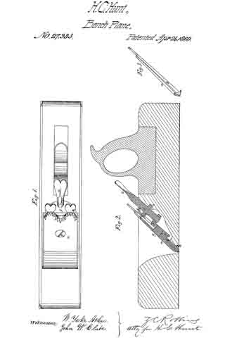
In the said drawings Figure 1, is a top view of my improved bench-plane; Fig. 2, a longitudinal section of the same, and Fig. 3, an edge view of the plane-bits detached from the stock.

The double bits a, b, in my improved bench-plane, are combined with each other, and with the plane-stock in the manner represented in Fig. 2, of the drawings, viz: the cutting bit b, has a central slit which passes from its upper end about two thirds the length thereof.

A metallic plate f, which is secured to the after side of the throat of the plane-stock, is of such a shape that it furnishes a metallic bearing surface for the cutting bit b, and also the requisite supporting and guiding bearings for the set-screw c. The screw shank of the set-screw c, is received into a screw-aperture in the angular nut d, which works in a slot in the throat-plate f. The cutting bit b, is combined with the front bit a, and also with the angular screw-nut d, by means of the screw g, which passes, first, through an aperture in the front bit a, then through the slit in the cutting bit, and then into the screw-aperture in the nut d. It will therefore be perceived that while the two bits a, and b, can be simultaneously moved outward or inward by turning the set-screw c, the cutting bit can also be readily adjusted so as to cause its cutting edge to project any desired distance beyond the closely embracing lower end of the front it, a.

It is well known that the cutting edge of a plane bit is more dulled and injured by the reverse movement of the plane over the surface of a board, than it is during its forward movement; which injurious action I have succeeded in entirely preventing by means of an attachment to the bits of my improved plane which I will now proceed to describe. A protecting metallic strap e, whose turned-up extremities are pivoted to the edges of the lower end of the front bit a, loosely embrace the lower end of the cutting bit b, so that when the plane is shoved forward, the said strap will swing freely upward into a notch which is formed in the plane-stock for its reception; but when a rearward movement is imparted to the plane, the said metallic strap will be drawn outward to a position that will cause it to elevate the front portion of the plane-stock a sufhcient distance above the face of the board that it may be operating upon, to prevent the cutting-bit from touching the surface of the board during the said reverse movement of the plane.

Having thus fully described my improved bench-plane, what I claim therein as new and desire to secure by Letters Patent, is —

Combining the metallic swinging strap e, with the bits of said plane substantially in the manner and for the purpose herein set forth.

The above specification of my improvement in bench-planes, signed and witnessed this 6th day of Feb., 1860.

H. C. HUNT.

Witnesses:
JAMES S. HARLAN,
ALBERT BALDWIN.

No. 28,946 – Plane Iron Sharpener (Joshua Turner) (1860)

[paiddownloads id=”87″]28946


UNITED STATES PATENT OFFICE.

_________________

J. TURNER, OF CAMBRIDGEPORT, MASSACHUSETTS, ASSIGNOR TO HIMSELF, AND F. GUILD, OF DEDHAM, MASSACHUSETTS.

PLANE-IRON SHARPENER.

_________________

Specification of Letters Patent No. 28,946, dated June 26, 1860.

_________________

To all whom it may concern:

Be it known that I, JOSHUA TURNER, of Cambridgeport, in the county of Middlesex and State of Massachusetts, have invented a new and useful Machine for Sharpening a Joiner’s Plane-Iron or other Tool of Like Nature; and I do hereby declare the same to be fully described and represented in the following specification and the accompanying drawings, of which —

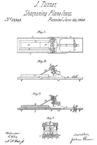
Figure 1, is a top view; Fig. 2, a side elevation; Fig. 3, a rear end view, and Fig. 4, a longitudinal and central section of it.

My said machine will answer for sharpening gouges and various other tools used by turners, joiners or other artificers.

In the drawings, A exhibits a whetstone as supported by a stand or table, B, or has a wooden socket piece S, resting in or on the table. This table is furnished with two parallel rails or ways C, C, or the equivalent thereof, for supporting and guiding an arched carriage, D, which is placed thereon, as represented. Over and sustained by such carriage, D, there is a separate tool carrier or holder, E, consisting of two bars a, b, and two clamp screws, d, e. Each screw passes through the upper bar d, and screws into the lower one so that when a plane iron F, is arranged between the two bars as shown, it may be clamped to them by the screws. Each bar of the carrier has a spherical projection or ball, f, or, g, extended from it as shown in the drawings. When the carrier is applied to the carriage D, one of these balls f, g, is to rest in an adjustable cup, socket or step G, which is provided with a screw, it, to screw vertically into the carriage. By means of the screw, the bevel of the edge of the plane iron may be varied within certain limits.

In rear of the carriage and the stone holder S, of the table B, there is an adjustable stop, I, which consists of a bar, i, projecting across the two rails, C, C, and held to the table by a clamp screw, k, which extends through a long slot, l, (made in the table) and screws into a piece of metal, m, extending across the slot and arranged underneath the table as shown in Fig. 4. The said slot serves to arrest the rearward movement of the carriage so that the plane-iron while being moved backward on the whetstone may not slip off the rear end of it.

In the operation of this machine, a person after having fixed a plane iron in the holder, E, and so as to rest at the bevel of its cutting edge on the stone, bears his hands on the holder, the iron and the carriage and moves the whole backward and forward longitudinally so as to cause the iron to be sharpened by the upper surface of the stone. While this is being done the spherical projection, that may be in the cup or socket of the carriage, will enable the plane iron to conform to the stone so as to wear equally while being moved on it.

By means of the two spherical projections applied to the cutter carrier or extended from it as described and represented we are able quickly to reverse the plane iron or turn it over so as to bring its opposite face in contact with the stone. This will be found particularly useful in removing a “wire edge” from the iron or for sharpening irons or tools which have two bevels to their cutting edge. Furthermore, the spherical projection enables a gouge to be turned laterally while being sharpened.

The machine constructed in manner and to operate as described is very useful to joiners or others for rapid and accurate sharpening of their plane irons or various other cutting tools.

I claim —

1. The combination and arrangement of the separate cutter carrier and its carriage with the whetstone supporter provided with parallel ways or equivalent means of guiding the carriage, the whole being to operate together substantially as and for the purpose specified.

2. The arrangement of ball bearings on opposite sides of the cutter carrier and to operate with a socket of the carriage as specified.

3. Making the socket or step adjustable vertically for the purpose explained.

4. The combination and arrangement of an adjustable stop with the table, the cutter carrier and its carriage applied to the table and with reference to the whetstone or its supporter as specified.

JOSHUA TURNER.

Witnesses:
R. H. EDDY,
F. P. HALE, Jr.

No. 29,962 – Molding Plane (Charles Fleming) (1860)

[paiddownloads id=”88″]29962


UNITED STATES PATENT OFFICE.

_________________

CHARLES FLEMING, OF YPSILANTI, MICHIGAN.

MOLDING-PLANE.

_________________

Specification of Letters Patent No. 29,962, dated September 11, 1860.

_________________

To all whom it may concern:

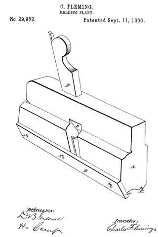
Be it known that I, CHARLES FLEMING, of the city of Ypsilanti, in Washtenaw county and State of Michigan, have invented a new and useful Improvement on Tools for Making Quarter-Round and Ogee Moldings, the board to be worked standing on edge, which I call “Fleming’s self-regulating quarter-round and ogee molding tool;” and I do hereby declare that the following is a full, clear, and exact description of the construction and operation of the same, reference being had to the annexed drawings, making a part of this specification, in which the figure represents a perspective of the quartenround tool as arranged and prepared for use.

A represents the body of the quarter round tool as commonly made.

B, B, represents the key holding the iron in place.

C, C, represents the iron-and E, the face gage. Parts so far described represent the common form of this tool.

D, represents a Wood or metal gage placed upon the side of the tool as seen in the figure, Where it is attached and kept in place by the screws S, S, S.

In the ogee tool the same gage is applied in the same manner and with like effect. This gage can be applied with perfect success to any ordinary 1/4 round or ogee tool.

To use the tools, either 1/4 round or ogee, attach the gage D, as seen in the drawings. Let the iron C, C, be so ground and set in the tool that it shall out a fair shaving at the face gage E, and scarcely cut at all at the side F. Set the board on edge in the vise of the workman, and apply the tool in the ordinary way, and when the work is complete, the gage D, will arrest the further working of the tool without thought or care on the part of the workman. While with the ordinary tool, without this self-regulating gage, the tool will continue to out until the whole board is wasted, and its operation must be carefully watched by the workman, to arrest it at the proper time, and then the work will not be as perfect and uniform as with the gage D, added.

I claim —

The combination of the guide strip (D) with 1/4 round and ogee molding planes, for the purposes set forth.

CHARLES FLEMING.

Signed in presence of —
D. B. GREENE,
H. CAMP.

No. 30,071 – Spoke Shave (Samuel Leonard) (1860)

[paiddownloads id=”89″]30071


UNITED STATES PATENT OFFICE.

_________________

SAMUEL LEONARD, OF BRIDGEWATER, MASSACHUSETTS.

SPOKE-SHAVE.

_________________

Specification of Letters Patent No. 30,071, dated September 18, 1860.

_________________

To all whom it may concern:

Be it known that I, SAMUEL LEONARD, of Bridgewater, in the county of Plymouth and State of Massachusetts, have invented a new and useful Improvement in the Spoke-Shave, and do hereby declare that the same is fully described and represented in the following specification and the accompanying drawings, of which —

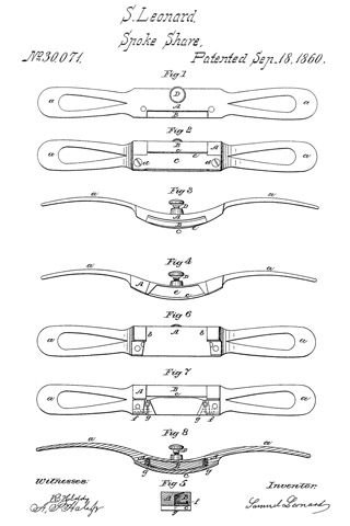
Figure 1 is a top view; Fig. 2, an under-side view; Fig. 3, a front elevation; Fig. 4, a rear elevation; and Fig. 5, a central and transverse section of a spokeshave containing my invention. Fig. 6 is an underside view of the stock divested of the cutter and its movable throat piece. Fig. 7 is an underside view of the throat piece and the stock as they appear when the knife is removed therefrom. Fig. 8 is a longitudinal section of the instrument taken through the springs of the throat piece.

The nature of my invention consists in an improved arrangement of the adjustable mouthpiece and its operative mechanism with respect to the stock and the cutter arranged in the stock in manner as hereinafter explained.

In the drawings, A, exhibits the stock as provided with two handles, a, a, and as constructed with a recess b, for the reception of an adjustable throat piece B, the recess and throat piece being arranged in the underside of the stock as shown in the drawings. The knife or cutter C extends longitudinally over the throat piece and in rear of its bearing face c, and is fastened at its two ends to the stock by screws, d, d. A chip throat or passage, e, is formed between the knife and the adjustable throat piece B, such chip throat or pqssage e, being made to open or have its discharging mouth at the back of the spoke shave as shown in the drawings. Near the two rearmost corners of the adjustable throat piece B, it is provided with two pivots or journals,f, f, which extend into bearings or pivot holes made in the stock and so as to enable the throat piece to be moved either toward or away from the cutting edge of the knife, its movement toward the said edge being effected by an adjusting screw, D, extending through the front part of the middle of the stock and against the throat piece, B, as shown in the drawings. Furthermore, springs, g, g, are arranged between the throat piece and the knife and near to opposite ends of the throat such springs operating to produce a counter movement of the adjustable throat.

I do not claim any improvement or any arrangement of parts as represented or as claimed in the United States Patent, No. 20855, for although I employ an adjustable bearing surface in front of the cutter and apply the same to the stock by means of a lever actuated by an adjusting screw, my invention consists in an improved arrangement and by means of it and with reference to the spoke-shave described in the said patent, I am enabled to dispense with a stock bearing surface, separate from the cutter or knife and arranged in rear thereof, and make the cutter itself or the lower surface thereof a bearing surface, and furthermore, the discharging mouth of the chip throat of my improved spoke shave is left free or has nothing in rear of it to obstruct the escape of shavings. In this way, while I gain all the advantages of the common spokeshave having no bearing in rear of its knife I also secure that of an adjustable throat and a bearing in front of the knife. Furthermore, I so arrange the space between the said throat piece and the stock, that no shaving passing into the throat can easily get between the said throat piece and the stock so as to clog the operation of the throat piece or prevent it from being moved by its adjusting screw.

I claim —

My improved arrangement of the adjustable mouthpiece and its operative mechanism with respect to the stock and the cutter
arranged in the stock as specified.

SAMUEL LEONARD.

Witnesses:
LAFAYETTE KEITH,
GEO. L. GATES.

No. 30,248 – Device For Securing Plane Bits (Theodore M. Richardson) (1860)

[paiddownloads id=”90″]30248


UNITED STATES PATENT OFFICE.

_________________

T. M. RICHARDSON, OF STOCKTON, MAINE.

DEVICE FOR SECURING PLANE-BITS.

_________________

Specification of Letters Patent No. 30,248, dated October 2, 1860.

_________________

To all whom it may concern:

Be it known that I, THEODORE M. RICHARDSON, of Stockton, in the county of Waldo and State of Maine, have invented an Improved Joiner’s Plane; and I do hereby declare that the same is fully described in the following specification and represented in the accompanying drawings, of which —

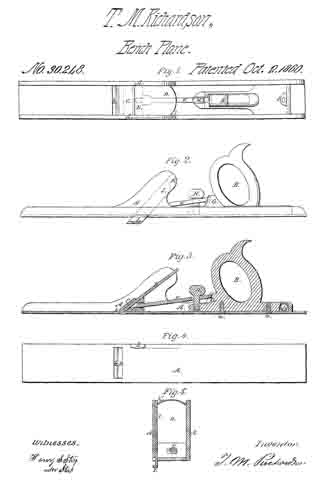
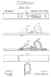
Figure 1, is a top view; Fig. 2, a side view; Fig. 3, a longitudinal section, and Fig. 4, an underside view of it. Fig. 5, exhibits a transverse section taken through the middle of the slider arranged in the side of the plane stock.

In these drawings A, denotes the stock, and, B, the handle thereof, the two being formed of metal or other suitable material and secured together by screws, a, a. The throat, b, of the plane stock is furnished with a stationary cap iron or cutter bearing, C, against the underside of which the cutter or plane iron, D, is arranged as shown in the drawings. The said plane iron is forced or clamped against the cap iron, C, by means of a wedge, E, a pitman, F, an inclined plane G, and a screw H, arranged relatively to each, the plane stock, the cutter and handle as shown in the drawings, that is to say, the wedge, E, is placed between the cutter and the base plate of the stock, while the inclined plane, G, is disposed in front of the handle and the pitman is made to extend from the inclined plane to the wedge and has the screw, H, carried through it and screwed into the front part of the base of the handle. By screwing down the said screw, the pitman will be forced down the inclined plane and by the latter will be driven forward against the wedge and thereby cause the said wedge to force the cutter or plane iron hard up against the bearing or cap iron, C. A slider, I, is arranged in the side of the plane stock and so as to slide into the recess, K, formed therein, and parallel or nearly so to the cutter. When the said slider is made to extend out of the socket or recess and beyond the lower face of the plane stock as shown in the drawings, it will serve as a guide for a workman in planing a “glue joint” or one surface at right angles to another the slider serving, in this respect, the purpose of an ordinary carpenter’s square, as its inner face, when the slider is extended shall stand at ip right angle with the underside of the stock.

In rear of the handle and in its base, I arrange a small glass spirit level L, and so as to stand transversely with respect to the plane stock, in other words at right angles with its sides, the said level being disposed as shown in Figs. 1 and 3. By this arrangement of the level it is covered and protected by the wrist of a workman while his hand may be grasping the handle, B, and thus the level is not so likely to becoine broken as would be the case were it arranged at the opposite end of the stock and in advance of the handle. My arrangement of the parts for holding the plane iron in place enables such iron to be removed and replaced with respect to the cap iron without requiring the aid of a screw driver or hammer.

I claim —

The arrangement of the clamp wedge E, the pitman, F, the inclined plane, G, and the screw, H, with the plane iron D, its cap bearing, C, and the stock A, substantially as described.

T. M. RICHARDSON.

Wtitnesses:
HENRY S. STAPLES,
ALEXANDER STAPLES, Jr.