
No. 294,724 – Router-Plane (Henry P. Cope) (1884)
UNITED STATES PATENT OFFICE.
_________________
HENRY F. COPE, OF DETROIT, MICHIGAN, ASSIGNOR OF
ONE-HALF TO JOHN H. BISSELL, OF SAME PLACE.
ROUTER-PLANE.
_________________
SPECIFICATION forming part of Letters Patent No. 294,724, dated March 4, 1884.
Application filed January 12, 1884. (No model.)
_________________
To all whom it may concern:
Be it known that I, HENRY P. COPE, of Detroit, in the county of Wayne and State of Michigan, have invented a new and useful Improvement in Router-Planes, of which the following is a specification.
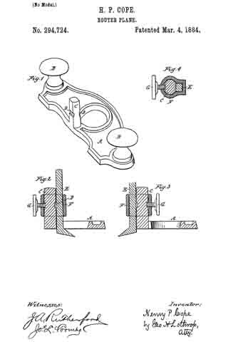
Figure 1 is a perspective, the iron and clamp being removed. Figs. 2 and 3 are vertical sections on the center of the iron, and Fig. 4 is a horizontal section through the thumb-screw which holds the iron in place.
My invention consists in an improvement in router-planes, whereby the iron can be set either within or without the stock, to adapt the plane for working into corners.
A represents the stock, having an opening therein, as is usual in router-planes. I usually make the stock of cast metal, thickened around the edges and opening, as shown in Fig. 1; but this is not material, as the stock may be made of any suitable shape and material.
B B represent handles secured to the stock.
C represents a post cast with or secured to the stock between one edge thereof and the opening therein. The opposite sides of post C are flattened, and a groove, D, cut therein on each of the two flattened sides.
E represents the plane-iron, which is shown as having a square shank, the sides thereof being the same or nearly the same width as the flattened sides of post C, and having a cutting end projecting at an angle from the lower end of the shank.
F represents a metal clamp having one portion adapted to fit post C, and another portion adapted to fit the shank of the iron, as clearly shown in Fig. 4.
G represents a set-screw working in a screw-thread tapped through clamp F, its end being adapted to engage with one of the grooves D, as clearly shown in Figs. 2, 3.
The operation of my invention is as follows: The iron being set as shown in Fig. 2, so that the cutting-edge projects through the opening in the stock, clamp F is slipped over the square shank of the iron and post C, until set-screw G is opposite one of the grooves D, when, by turning up set-screw G, the iron E is firmly clamped to post C, and the plane is ready for all work which can be done by an ordinary router-plane. By loosening the set-screw the iron can be raised or lowered to suit the work to be done. When it is necessary to rout out a channel close to a projecting piece which cannot be reached by the ordinary router-plane, because the stock comes in contact with the projecting piece before the iron reaches the end of the channel, I shift the iron E to the outer side of post C and reverse clamp F, as shown in Fig. 3, so that the iron works entirely outside of the stock and will work close up to a projection.
It is evident that many alterations may be made in the shape of the post, the shape of the iron, and the manner of securing the iron to the post, so that its cutting-edge may be placed at will inside or outside of the stock, without departing from the principle of my invention.
What I claim as my invention, and desire to secure by Letters Patent, is —
1. A router-plane having a support secured to its stock between one edge thereof and an opening therethrough, combined with means for connecting the plane-iron to either the inner or the outer portion of said support, to bring the cutting-edge of the plane-iron within or without the stock, substantially as described.
2. A router-plane having a post secured to its stock between one edge thereof and an opening therethrough, and a clamp adapted to secure the plane-iron to either the inner or outer side of said post, substantially as shown and described.
3. A router-plane having a post, C, secured to its stock, and having grooves D on its inner and outer sides, respectively, combined with the plane-iron E, the clamp F, and the set-screw G, passing through the clamp and entering one of the grooves, for holding the plane-iron on either the inner or the outer side of the post, to bring the cutting-edge of said iron within or without the stock, substantially as described.
H. P. COPE.
Witnesses:
SUMNER COLLINS,
GEO. H. LOTHROP.