
No. 199,956 – Improvement In Bench-Planes (Joseph B. Boyce) (1878)
UNITED STATES PATENT OFFICE.
_________________
JOSEPH B. BOYCE, OF LOCKPORT, NEW YORK.
IMPROVEMENT IN BENCH-PLANES.
_________________
Specification forming part of Letters Patent No. 199,956, dated February 5, 1878; application filed January 12, 1878.
_________________
To all whom it may concern:
Be it known that I, JOSEPH B. BOYCE, of Lockport, in the county of Niagara and State of New York, have invented a new and useful Improvement in Bench-Planes, which improvement is fully set forth in the following specification and accompanying drawings, in which latter —
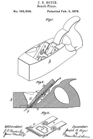
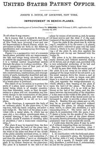
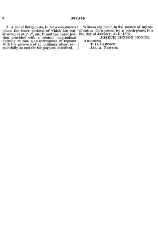
Figure 1 is a perspective view of a common bench-plane provided with my improvement, the bits and wedge being removed in order to exhibit the improvement more fully. Fig. 2 is a vertical central longitudinal section through the plane in working condition. Fig. 3 is a perspective view of that part of the plane which I have improved.
The nature of my invention consists in certain construcinons, combinations, and arrangements of parts, hereinafter described and specifically claimed, whereby an improved adjustable metal lining for the throat and mouth of a bench-plane is produced.
The object of my invention is to protect the parts of a plane most exposed to wear by a metal lining which is of simpler construction than heretofore made, so that its application to a plane will not necessitate any material change in the construction of the plane to which it may be applied, and which may be as easily applied to an old as to a new plane.
In the drawings, A represents the body of an ordinary plane; B, the plane-iron; C, the cap-iron, with the usual coupling set-screw c and wedge D. The bed b of the plane is provided with a metal plate, E, which has an open slot, e, two oblong countersunk slots, e1, a central opening, e2, and an oblong mouth, F, which mouth F consists of abutting sides or shoulders f and a transverse connecting-strip, f’.
The plate E may be inserted from the face of the plane after the bed b of the plane has, if needs be, been reduced to receive it, and the wood at the sides and front of the mouth of the plane suitably mortised away, in order to receive the shoulders f and connectionf’, and thus the shoulders f serve as abutments for preventing the upward movement of the plate E by violent strains on the plane-iron. The plate E is fastened to the bed b of the plane by means of set-screws g, and, by means of these screws and the slots e1 e1, the readjustment of the plane-face may also be effected.
Upon the plate E the plane-iron B, with its cap C, coupled to it by the screw c, is placed, and its screw c allowed to pass into the usual recess a, which is in rear of the oblong opening e of the plate E, and, thus applied, the plane-iron and its cap are fastened with the wedge D.
The plane A is, by this construction, in a ready manner, and without material change of its throat, and at slight cost, provided with a very substantial protection of its bed and other parts liable to injury from wear.
It will be seen that while the center part of the plate E is cut away at e to admit of the passage of the large head of the set-screw c, in the usual manner, down the recess a, and at the opening e2, in order to lessen cost, still there is a continuous metal surface at either side, just opposite the wedge-abutments a’, which affords a firm bearing of the plate E upon the bed b of the plane. The plate E, above its shoulders f f is as wide as the throat or the bed of the plane, and the distance between the inner sides of the shoulders f is the same as the width of the plate E; consequently the width of the throat need not be increased in order to provide a plane with a plate, E. Besides this, any plane, new or old, may be so provided and improved without weakening the plane, by simply mortising from below, to admit the shoulders f f and connecting-strip f’. The lower end of the plate E, in conjunction with the parts f and f’, forms a lining for the mouth of the plane, and constitutes a part of the plane around its mouth, thereby protecting the plane against premature wear in and around the mouth.
I would state that the plate E may be solid at e2 without departing from my invention.
Having described my invention, what I claim as new, and desire to secure by Letters Patent, is —
1. In combination with the body and plane-iron of a carpenter’s plane, the lining-plate E, having slots e1 e1 and a longitudinal opening, e, and a mouth, F, formed with abutting shoulders f united as at f’, substantially as and for the purpose set forth.
2. A metal lining-plate, E, for a carpenter’s plane, the lower portions of which are constructed as at f, f’, and F, and the upper portion provided with a central longitudinal opening or slot, e, to correspond or register with the groove a of an ordinary plane, substantially as and for the purpose described.
Witness my hand, in the matter of my application for a patent for a bench-plane, this 8th day of January, A. D. 1878.
JOSEPH BENSON BOYCE.
Witnesses:
T. D. BABCOCK,
JAS. A. NEWTON.