
No. 203,442 – Improvement In Bench-Planes (Robert S. Griffin) (1878)
UNITED STATES PATENT OFFICE.
_________________
ROBERT S. GRIFFIN , OF WORCESTER, MASSACHUSETTS.
IMPROVEMENT IN BENCH-PLANES.
_________________
Specification forming part of Letters Patent No. 203,442, dated May 7, 1878; application filed April 6, 1878.
_________________
To all whom it may concern:
Be it known that I, ROBERT S. GRIFFIN, of Worcester, in the county of Worcester and State of Massachusetts, have invented a new and valuable Improvement in Planes; and I do hereby declare that the following is a full, clear, and exact description of the construction and operation of the same, reference being had to the annexed drawings, making a part of this specification, and to the letters and figures of reference marked thereon.
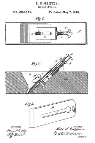
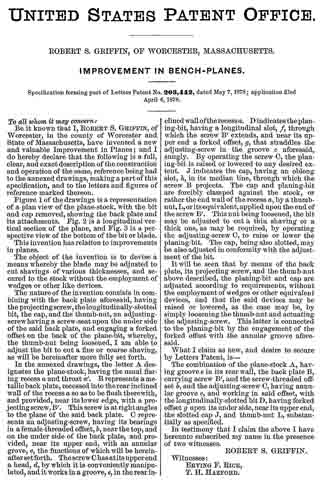
Figure 1 of the drawings is a representation of a plan view of the plane-stock, with the bit and cap removed, showing the back plate and its attachments. Fig. 2 is a longitudinal vertical section of the plane, and Fig. 3 is a perspective view of the bottom of the bit or blade.
This invention has relation to improvements in planes.
The object of the invention is to devise a means whereby the blade may be adjusted to cut shavings of various thicknesses, and secured to the stock without the employment of wedges or other like devices.
The nature of the invention consists in combining with the back plate aforesaid, having the projecting-screw, the longitudinally-slotted bit, the cap, and the thumb-nut, an adjusting-screw having a screw-seat upon the under side of the said back plate, and engaging a forked offset on the back of the plane-bit, whereby, the thumb-nut being loosened, I am able to adjust the bit to cut a fine or coarse shaving, as will be hereinafter more fully set forth.
In the annexed drawings, the letter A designates the plane-stock, having the usual flaring recess a and throat a’. B represents a metallic back plate, recessed into the rear inclined wall of the recess a. so as to be flush therewith, and provided, near its lower edge, with a projecting screw, B’. This screw is at right angles to the plane of the said back plate. C represents an adjusting-screw, having its bearings in a female-threaded offset, b, near the top, and on the under side of the back plate, and provided, near its upper end, with an annular grove, c, the functions of which will be hereinafter set forth. The screw C has at its upper end a head, d, by which it is conveniently manipulated, and it works in a groove, e, in the rear inclined wall ofthe recess a. D indicates the planing-bit, having a longitudinal slot, f, through which the screw B’ extends, and near its upper end a forked offset, g, that straddles the adjusting-screw in the groove c aforesaid, snugly. By operating the screw C, the planing-bit is raised or lowered to any desired extent. J indicates the cap, having an oblong slot, h, in its median line, through which the screw B projects. The cap and planing-bit are forcibly clamped against the stock, or rather the end wall of the recess a, by a thumb-nut, L, or its equivalent, applied upon the end of the screw B’. This nut being loosened, the bit may be adjusted to cut a thin shaving or a thick one, as may be required, by operating the adjusting-screw C, to raise or lower the planing-bit. The cap, being also slotted, may be also adjusted in conformity with the adjustment of the bit.
It will be seen that by means of the back plate, its projecting screw, and the thumb-nut above described, the planing-bit and cap are adjusted according to requirements, without the employment of wedges or other equivalent devices, and that the said devices may be raised or lowered, as the case may be, by simply loosening the thumb-nut and actuating the adjusting-screw. This latter is connected to the planing-bit by the engagement of the forked onset with the annular groove aforesaid.
What I claim as new, and desire to secure by Letters Patent, is —
The combination of the plane-stock A, having groove e in its rear wall, the back plate B, carrying screw B’, and the screw-threaded offset b, and the adjusting-screw C, having annular groove c, and working in said offset, with the longitudinally-slotted bit D, having forked offset g upon its under side, near its upper end, the slotted cap J, and thumb-nut L, substantially as specified.
In testimony that I claim the above I have hereunto subscribed my name in the presence of two witnesses.
ROBERT S. GRIFFIN.
Witnesses:
ERVING F. RICE,
T. H. HAZFORD.