No. 207,599 – Improvement In Bench-Planes (Henry A. Foss) (1878)

[paiddownloads id=”294″]207599


UNITED STATES PATENT OFFICE.

_________________

HENRY A. FOSS, OF PINE MEADOW, CONNECTICUT, ASSIGNOR TO PHILIP E. CHAPIN, OF SAME PLACE.

IMPROVEMENT IN BENCH-PLANES.

_________________

Specification forming part of Letters Patent No. 207,599, dated September 3, 1878; application filed April 15, 1878.

_________________

To all whom it may concern:

Be it known that I, HENRY A. FOSS, of Pine Meadow, in the county of Litchfield and State of Connecticut, have invented certain new and useful Improvements pertaining to a Carpenter’s Plane, of which the following is a specification, reference being had to the accompanying drawings, where —

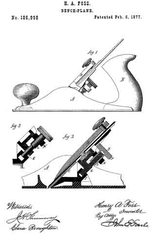
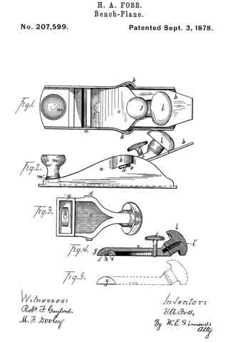
Figure 1 is a top view of a plane embodying my improvements. Fig. 2 is a side view of same. Fig. 3 is a bottom view of the fastening-lever. Fig. 4 is a view of the fastening-lever in central longitudinal section. Fig. 5 is a side view of the lower end of the fastening-lever.

The letter a denotes the body or stock of a metallic plane. b denotes the plane-iron, which may or may not be supplemented by a cap-iron lying on a proper bed and running down to the throat. The letter c denotes the fastening-lever, bearing on its sides the fulcrum-ears d d, resting in the fulcrum-mortises e e, which are made in the plane-stock, provided near the upper end with the tightening-screw f and at the lower end with the rocking end g, which is pivoted to the fastening-lever in such shape as to allow it to rock and adjust itself to bear squarely and flatly on the plane-iron. To secure this rocking motion, the lower end of the fastening-lever is provided with the pivot-pin h, which runs through a corresponding pin-hole, i, in the rocking end, and is provided with a head on the under side. Preferably the spring j is also secured on this pin, bearing against the under side of the rocking end.

The sides of the plane-body are provided with or shaped into the swells k k, and the fulcrum-mortises e e are made just underneath these swells. These swells allow the passage of the fulcrurn-ears d d down to the fulcrum-mortises. Then, by sliding the fastening-lever slightly forward, the ears d d are carried to the forward ends of the mortises, which are inwardly shouldered, so that the ears lock under at this point. This construction not only allows the fulcrum-mortises to be cast, but the swells give a good gripe for the hand of the operator.

The letter l denotes a knob or handle, fastened to the fastening-lever c by having the screw l’ cast in or projecting from the fastening-lever, and running into the knob. Another mode of fastening on this or such a knob is illustrated by the knob m, which is driven into the ring m’, cast on or projecting from the floor of the plane-stock.

I claim as my invention —

1. In combination with the plane-body and plane-iron, the fastening-lever c, provided with the rocking end g, substantially as described, and for the purpose set forth.

2. The fastening-lever c, provided with the screw l’, and combined with the knob l.

HENRY A. FOSS.

Witnesses:
JAMES WILEY,
O. T. HUNGERFORD.

No. 186,998 – Improvement In Bench-Planes (Henry A. Foss) (1877)

[paiddownloads id=”275″]186998


UNITED STATES PATENT OFFICE.

_________________

HENRY A. FOSS, OF NEW BRITAIN, CONNECTICUT.

IMPROVEMENT IN BENCH-PLANES.

_________________

Specification forming part of Letters Patent No. 186,998, dated February 6, 1877; application filed January 9, 1877.

_________________

To all whom it may concern:

Be it known that I, HENRY A. FOSS, of New Britain, in the county of Hartford and State of Connecticut, have invented a new Improvement in Bench-Planes; and I do hereby declare the following, when taken in connection with the accompanying drawings and the letters of reference marked thereon, to be a full, clear, and exact description of the same, and which said drawings constitute part of this specification, and represent, in —

Figure 1, a side view, and in Fig. 2 a longitudinal central section; and Fig. 3, a modiication.

This invention relates to an improvement in the method of adjusting the bit or iron of bench-planes. It consists in the arrangement of a differential screw, one portion of which is connected with the bit, the other with the stationary nut, and so that, by turning the screw, the iron will be moved only the difference between the thread of the two parts, as more fully hereinafter set forth.

A is the body of the plane; B, the handle; C, the bit or plane-iron, held in place by the clamp D, all in substantially the usual manner. Referring to Fig. 2, the screw is shown as made in two parts. In rear of the bit C, and in a line substantially parallel thereto, one part, E, of the screw is arranged, its lower end supported in a suitable socket, F, and with an arm, G, extending toward the bit, and connected therewith through the cap-screw H or otherwise, so that the movement of the screw will move the bit accordingly. Onto the part E of the screw the second tubular part L of the screw is set, threaded both inside and out, the inside thread corresponding to the thread of the part E, and either coarser or finer than the thread on the outside of the part L — that is, so that there be a substantial diierence in the two threads. The part L is placed in a stationary nut, N, and is provided with a suitable head, P, by which it may be turned. The screw-threads are both the same — that is, both right or left hand threads, as may be desirable — therefore, by turning the part L so as to run it downward, the part E will correspondingly run up into the part L, and the downward movement of the part L will be only the diderence between the two threads; as, for instance, suppose the external thread ofthe part L to be twenty, and that of the part E thirty, then a full revolution of the part L would run that screw down one-twentieth of an inch, and draw the part E up one-thirtieth of an inch; hence the downward movement of the part L would be one-sixtieth of an inch, and the bit would be moved accordingly. This enables a very iine and delicate adjustment of the bit, but yet positive and firm in its operation.

Instead of making the differential screw in two parts, as in Fig. 2, it may be a single piece, as in Fig. 3, the upper part L engaging in the nut in the same manner as the first illustration, the lower part E working in a connection which extends to the bit; making therefore the same difference between the two parts E and L, the same result will be attained.

I am aware that various devices have been used in bench-planes for the mechanical adjustment of the bit, and that among these a single screw has been used; I therefore do not wish to be understood as broadly claiming such a mechanical device; but

What I do claim as my invention, and desire to secure by Letters Patent, is —

ln combination with the body and bit of a bench-plane, a differential screw, one part working in connection with the bit, the other in a stationary nut, substantially as and for the purpose described.

HENRY A. FOSS.

Witnesses:
AUSTIN HART,
MICHAEL T. TOOMEY.