
No. 17,618 – Holding And Adjusting Plane Irons In Their Stocks (Willard W. Chipman) (1857)
UNITED STATES PATENT OFFICE.
_________________
WILLARD W. CHIPMAN, OF LOWELL, MASSACHUSETTS.
METHOD OF HOLDING AND ADJUSTING PLANE-IRONS IN THEIR STOCKS.
_________________
Specification of Letters Patent No. 17,618, dated June 23, 1857.
_________________
To all whom it may concern:
Be it known that I, WILLARD W. CHIPMAN, of Lowell, in the county of Middlesex and Commonwealth of Massachusetts, have invented certain new and useful Improvements in Apparatus for Holding and Adjusting Plane-Irons; and I do hereby declare the following to be a full, clear, and exact description thereof, reference being had to the accompanying drawings and to the letters of reference marked thereon.
Similar letters of reference in each of the several figures refer to like parts.
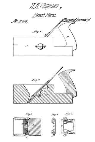
Figure 1 is a side elevation of a plane with my improvements attached. Fig. 2 is a longitudinal vertical section of the same. Fig. 3 is a cross section perpendicular to the direction of the plane iron. Fig. 4. is a plan of a part of the apparatus, shown detached from the plane stock. Fig. 5 is an end view of the same.
A represents the stock, or main part of the plane. B is the handle, C is the iron, or cutting tool, D is the cap which is secured on the face of C in the usual manner by means of the screw F. This cap may, or may not be used.
Fastened to the back of the “iron” C is a double V or sliding piece E which has a slot running longitudinally through the middle of it large enough to admit the head of the screw F.
G, G is a small metallic frame having a V shaped groove on each side in which the sliding piece E is supported. A suitable place is cut out in the plane stock directly beneath the iron C to receive this frame G and it is secured therein by means of screws.
H, H’ are frogs or wedge shaped pieces secured in the grooves of the frame G, G by means of a joint so that one end is at liberty to swing in or out. These frogs are operated upon by means of the thumb screws I, I’, which screw through the sides of frame G and press against the movable end of the frogs. The heads of the thumb screws I, I’ are sunk in recesses made, one on each side of the plane stock and just large enough to allow the thumb and finger to have a fair chance to turn the screws. Now when the frogs are thrown back in the grooves, the slide E is at liberty to move up or down in them (the grooves) freely, and the “plane iron” can be adjusted to its proper place, which being done, the thumb screws are turned up against the frogs, and these bind or wedge the sliding piece E into the grooves, and thus the plane iron is secured firmly in its place. One advantage in this manner of securing the plane iron is, that it leaves the mouth of the plane through which the shavings come perfectly smooth and free from all the obstructions that are found in the common plane, so that the shavings cannot clog in the mouth and cause trouble to the operator. Another advantage is in the facility it affords of adjusting the iron to the right gage, and also of setting it. square. If, as it often happens, one side of the edge of the iron projects through the mouth more than the other, then we must loosen the screw on the side where the edge shows least and screw up the other, until the edge comes into the right position. This simple and positive operation is an evident advantage over the old uncertain way of rapping the top of the iron with a hammer.
Having thus described my invention, what I claim as new and desire to secure by Letters Patent, is —
The use and application of the apparatus for holding and adjusting the plane iron, substantially as, and for the purpose described.
In witness whereof I have hereunto set my signature this twenty fifth day of May A. D. 1857.
WILLARD W. CHIPMAN.
In presence of us —
N. WRIGHT,
O. E. CUSHING.