
No. 17,286 – Joiner’s Plane (Benjamin I. Lane) (1857)
UNITED STATES PATENT OFFICE.
_________________
BENJAMIN I. LANE, OF NEWBURYPORT, MASSACHUSETTS.
JOINER’S PLANE.
_________________
Specification of Letters Patent No. 17,286, dated May 12, 1857.
_________________
To all whom it may concern:
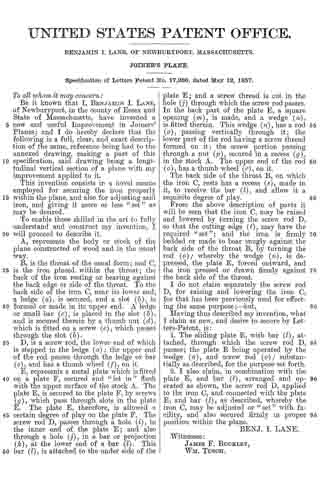
Be it known that I, BENJAMIN I. LANE, of Newburyport, in the county of Essex and State of Massachusetts, have invented a new and useful Improvement in Joiners’ Planes; and I do hereby declare that the following is a full, clear, and exact description of the same, reference being had to the annexed drawing, making a part of this specification, said drawing being a longitudinal vertical section of a plane with my improvement applied to it.
This invention consists in a novel means employed for securing the iron properly within the plane, and also for adjusting said iron, and giving it more or less “set” as may be desired.
To enable those skilled in the art to fully understand and construct my invention, I will proceed to describe it.
A, represents the body or stock of the plane constructed of wood and in the usual way.
B, is the throat of the usual form; and C, is the iron placed within the throat; the back of the iron resting or bearing against the back edge or side of the throat. To the back side of the iron C, near its lower end, a ledge (a), is secured, and a slot (b), is formed or made in its upper end. A ledge or small bar (c), is placed in the slot (b),
and is secured therein by a thumb nut (d), which is fitted on a screw (e), which passes through the slot (b).
D, is a screw rod, the lower end of which is stepped in the ledge (a) ; the upper end of the rod passes through the ledge or bar (c), and has a thumb wheel (f), on it.
E, represents a metal plate which is fitted on a plate F, secured and “let in” flush with the upper surface of the stock A. The plate E, is secured to the plate F, by screws (g), which pass through slots in the plate E. The plate E, therefore, is allowed a certain degree of play on the plate F. The screw rod D, passes through a hole (i), in the inner end. of the plate E; and also through a hole (j), in a bar or projection (k), at the lower end of a bar (l). This bar (l), is attached to the under side of the plate E; and a screw thread is out in the hole (j) through which the screw rod passes. In the back part of the plate E, a square opening (m), is made, and a wedge (n), is fitted therein. This wedge (n) , has a rod (o), passing vertically through it; the lower part of the rod having a screw thread formed on it; the screw portion passing through a nut (p), secured in a recess (g), in the stock A. The upper end of the rod (o), has a thumb wheel (r), on it.
The back side of the throat B, on which the iron C, rests has a recess (s), made in it, to receive the bar (l), and allow it a requisite degree of play.
From the above description of parts it will be seen that the iron C, may be raised and lowered by turning the screw rod D, so that the cutting edge (t), may have the required “set”; and the iron is firmly bedded or made to bear snugly against the back side of the throat B, by turning the rod (o); whereby the wedge (n), is depressed, the plate E, forced outward, and iron pressed or drawn firmly against the the back side of the throat.
I do not claim separately the screw rod D, for raising and lowering the iron C, for that has been previously used for effecting the same purpose; — but,
Having thus described my invention, what I claim as new, and desire to secure by Letters Patent, is:
1. The sliding plate E, with bar (l), attached, through which the screw rod D, passes; the plate E being operated by the wedge (n), and screw rod (o); substantially as described, for the purpose set forth.
2. I also claim, in cornbination with the plate E, and bar (l), arranged and operated as shown, the screw rod D, applied to the iron C, and connected with the plate E, and bar (l), as described, whereby the iron C, may be adjusted or “set” with facility, and also secured firmly in proper position within the plane.
BENJ. I. LANE.
Witnesses:
JAMES F. BUCKLEY,
WM. TUSCH.