
No. 17,332 – Joiner’s Plane (James Lashbrooks) (1857)
UNITED STATES PATENT OFFICE.
_________________
JAMES LASHBROOKS, OF OWENSBORO, KENTUCKY.
JOINER’S PLANE.
_________________
Specification of Letters Patent No. 17,332, dated May 19, 1857.
_________________
To all whom it may concern:
Be it known that I, JAMES LASHBROOKS, of Owensboro, in the county of Daviess and State of Kentucky, have invented certain new and useful Irnprovernents in Hand-Planes; and I do hereby declare that the following is a full, clear, and exact description thereof, reference being had to the accompanying drawings and to the letters of reference marked thereon.
The nature of nay invention consists in the use of a curved bit whereby I am enabled to use a handle on all planes however short without any inconvenience.
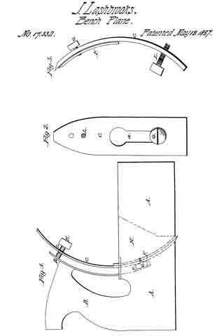
In order that those skilled in the art may use and manufacture my invention I will proceed to describe operation and construction. In the accompanying drawings which make a part of this specification Figure 1 is a side elevation. Fig. 2 is a plan view of the bit. Fig. 3 is a side elevation of the bit.
In Fig. 1 A is the stock, B the handle, C the bit, D a plate of steel extending into the stock and attached to the handle. L is a screw passing through the bit C for the purpose of holding in its position, E the head of said screw. G seen in dotted line shows a screw for attaching bit F to bit C. g is a slot in the stock in which screw G works.
In Fig. 2 C is the bit, L the screw, a a slot through which screw G passes attaching the two bits.
In Fig. 3 C the main bit, F the cap bit, G screw for attaching them, L screw for stationing the bits at any desired point.
In the operation of my invention the bit and cap are first fastened together by means of the screw G and adjusted to the position required in the stock and then set to the depth required for planing by ineans of screw L which presses against plate D, D. The plane is then ready for use. It will be seen that as the bit C is pressed by means of screw L against plate D the effect of the leverage is to press the lower end of the bit firmly against the lower side of the plane stock through which it passes thus making a more solid and firm plane than by any other device known, doing away entirely with wedges in my curved bit plane.
One of the peculiar advantages of my invention consists in causing the bit to curve forward and thus allowing me room to set a handle on all short or smoothing planes which cannot be done by any other shaped bit heretofore known and which object is of great iinportance in short planes. It is also applicable to all planes.
Having thus described my invention what I claim is —
The curved plane iron C and cap F in combination with the curved back rest and slotted plate D operating as described and for the purpose set forth.
JAMES L ASHBROOKS.
Witnesses:
HENRY DUGAN,
JOHN LASHBROOK.