No. 16,889 – Carpenter’s Plane (M.B. Tidey) (1857)

[paiddownloads id=”38″]16889


UNITED STATES PATENT OFFICE.

_________________

M. B. TIDEY, OF ITHACA, NEW YORK.

CARPENTER’S PLANE.

_________________

Specification of Letters Patent No. 16,889, dated DMarch 24, 1857.

_________________

To all whom it may concern:

Be it known that I, M. B. TIDEY, of Ithaca, in the county of Tompkins and State of New York, have invented a new and Improved Mode of Constructing Bench-Planes; and I do hereby declare that the following is a full and clear description of the same, reference being had to the accompanying drawings, forming part of this specification, in which —

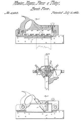
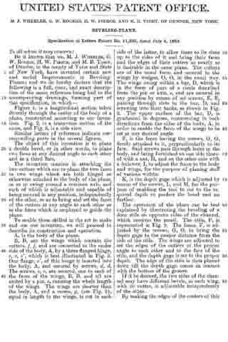
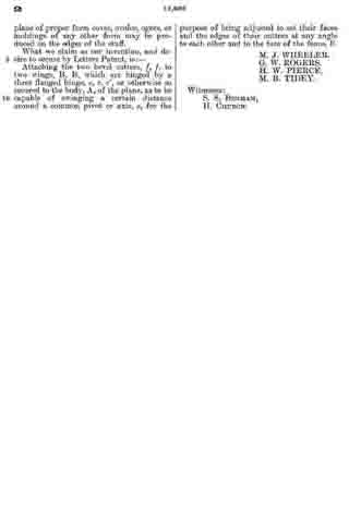
Figure 1 is a View of the cavity or throat opening of the plane stock as constructed for the reception of the bit-case. Fig. 2 is a reverse view of the same and Fig. 3 is a longitudinal sectional view thereof. Fig. 4; is a bit-case to be applied to said cavity and Fig. 5 is a view of the lower extremity thereof. Fig. 6 is the same as Fig. 1 with the bit-case applied, and Fig. 7 is a reverse view of the same. Fig. 8 is a view of the plane complete as invented and constructed by me.

Similar letters of reference indicate corresponding parts in these several figures.

The object of this invention is, first to simplify the manufacturing of planes; second to render them more durable; third to retain a uniform mouth; fourth to obviate their clogging and fifth the retention of the essential part of the plane when the stock is worn out.

The following description will enable those skilled in the art to make and use my invention.

The mode of my invention consists in the construction of planes of wood and in the usual way with the exception of the cavity or throat opening which is essentially different as will be seen hereafter.

I construct in the plane stock a cavity of uniform width as denoted by lines a, Figs. 1, 2, 6, 7, and 8, which terminates longitudinally at lines 5, Figs. 1, 2, 3, 6, 7, and 8. Fig. 1 is an upper view of said cavity showing also the adjustable screw B with supporting nut C and screw holes f, f, also finishing cuts c, c. Fig. 2 is a reverse view of the same showing the face of the plane. The lines F, F, F, F, Fig. 3, represents the back face and the lower part of the front face of the cavity or throat opening and are to be made parallel with each other or nearly so, the object of which is to prevent any space or opening at point D, Fig. 7, by drawing up the bit-case for the purpose of refacing the plane. In the cavity as thus constructed I apply the metallic bit-case (Fig. 4) as seen at A, Fig. 6, which is secured thereto by screws d d through slots e, e, entering nut f, said nut being a rod of iron passing through the plane stock for that purpose. The bit-case passes through the stock, its lower extremity constituting a section of the plane’s face being provided with a mouth q and other formations necessary to the reception of the bit and its means of fastening thereto. The bit-case I arrange so as to be adjusted according to the wear or diminution of the plane’s face, for which purpose I throw the upper extremity of the case back making a projection at right angles with its bed A, which is provided with recess g, which is received by groove h, of adjustable screw B, by the operation of which the bit-case may be set at pleasure, slots e e, Figs. 4 and 6, admitting its passage under screw heads d, d, when loosened.

What I claim as my invention and desire to secure by Letters Patent is:

The application to the cavity of the plane stock of a metallic bit-case and so applying it that its lower extremity shall constitute a part of the plane’s face constructed and operated substantially for the purpose and in the way set forth.

M. B. TIDEY.

Witnesses:
WM. ANGLE,
WM. F. PECK.

No. 11,235 – Beveling Plane (Wheeler, Rogers, Pierce & Tidey) (1854)

[paiddownloads id=”13″]11235


UNITED STATES PATENT OFFICE.

_________________

M. J. WHEELER, G. W. ROGERS, H. W. PIERCE AND M. B. TIDEY, OF DUNDEE, NEW YORK.

BEVELING-PLANE.

_________________

Specification of Letters Patent No. 11,235, dated July 4, 1854.

_________________

To all whom it may concern:

Be it known that we, M. J. WHEELER, G. W. ROGERS, H. W. PIERCE, and M. B. TIDEY, of Dundee, in the county of Yates and State of New York, have invented certain new and useful Improvements in Beveling-Planes; and do not hereby declare that the following is a full, clear, and exact description of the same, reference being had to the accompanying drawings, forming part of the specification, in which–

Figure 1, is a longitudinal section taken directly through the center of the body of a plane, constructed according to our invention. Fig. 2, is a side view.

Similar letters of reference indicate corresponding parts in the several figures.

The object of this invention is to plane a double bevel, or in other words, to plane two faces at any desired angle to each other and to a third face.

The invention consists in attaching the two cutters which are to plane the two faces to two wings which are both hinged or otherwise attached to the body of the plane, so as to swing around a common axis, and each of which is adjustable and capable of being secured in any position, independently of the other, so as to bring and set the faces of the cutters at any angle to each other or to the fence which is employed to guide the plane.

To enable those skilled in the art to make and use our invention, we will proceed to describe its construction and operation.

A, is the body of the plane.

B, B, are the wings which contain the cutters, f, f, and are connected to the under side of the body, A, by a three flanged hinge, c, c, c’, which is best illustrated in Fig. 2. One flange, c’, of this hinge is inserted into the body, A, and secured by screws, d, d. The screws, c, c, are secured, one to each of the faces of the wings, B, B, and all are united by a pin, e, running the whole length of the wings. The wings are shorter than the body, A, and a recess, g, (see Fig. 2), equal in length to the wings, is cut in each side of the latter, to allow them to lie close up to the sides of it and bring their faces and the edges of their cutters as nearly as is desirable in the same plane. The cutters are of the usual form and secured in the wings by wedges, O, ), in the usual way. The wings swing within a bar, D, which is in the form of part of a circle described from the pin or axis, e, and are secured in any position by means of set screws, E, E, passing through slots in the bar, D, and screwing into their backs, as shown in Fig. 2. The upper surface of the bar, D, is graduated in degrees, commencing in both directions from the sides of the body, A, in order to enable the faces of the wings to be set at any desired angle.

F, is the fence having the screws, G, G, firmly attached to it, perpendicularly to its face. Said screws pass through holes in the body, and being furnished on one side thereof with a nut, H, and on the other side with a follower, I, to adjust the fence to the body and wings, for the purpose of planing stuff of various widths.

K, is the depth gage which is adjusted by means of the screws, L, and M, for the purpose of enabling the tool to cut to the required depth to perfect the bevel and no farther.

The operation of the plane can be best explained by illustrating the beveling of a door stile on opposite sides of the channel, which receives the panel. The stile, P, is represented in Fig. 2. The fence, F, is adjusted by the screws, G, G, to bring the depth gage to the proper distance from the side of the stile. The wings are adjusted to set the edges of the cutters at the proper angle to each other and to the face of the stile, and the depth gage is set to the proper depth. The edge of the stile is then planed down till the depth gage comes in contact with the bottom of the groove.

If it be desired, the two sides of the channel may have different bevels, as each wing, with its cutter, is adjustable independently of the other.

By making the edges of the cutters of this plane of proper form coves, ovolos, ogees, or moldings of any other form may be produced on the edges of the stuff.

What we claim as our invention, and desire to secure by Letters Patent, is:–

Attaching the two bevel cutters, f, f, to two wings, B, B, which are hinged by a three flanged hinge, c, c, c’, or otherwise so secured to the body, A, of the plane, as to be capable of swinging a certain distance around a common pivot or axis, e, for the purpose of being adjusted to set their faces and the edges of their cutters at any angle to each other and to the face of the fence, F.

M. J. WHEELER.
G. W. ROGERS.
H. W. PIERCE.
M. B. TIDEY.

Witnesses:
S. S. BENHAM,
H. CHURCH.