No. 16,889 – Carpenter’s Plane (M.B. Tidey) (1857)

UNITED STATES PATENT OFFICE.
_________________
M. B. TIDEY, OF ITHACA, NEW YORK.
CARPENTER’S PLANE.
_________________
Specification of Letters Patent No. 16,889, dated DMarch 24, 1857.
_________________
To all whom it may concern:
Be it known that I, M. B. TIDEY, of Ithaca, in the county of Tompkins and State of New York, have invented a new and Improved Mode of Constructing Bench-Planes; and I do hereby declare that the following is a full and clear description of the same, reference being had to the accompanying drawings, forming part of this specification, in which —
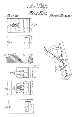
Figure 1 is a View of the cavity or throat opening of the plane stock as constructed for the reception of the bit-case. Fig. 2 is a reverse view of the same and Fig. 3 is a longitudinal sectional view thereof. Fig. 4; is a bit-case to be applied to said cavity and Fig. 5 is a view of the lower extremity thereof. Fig. 6 is the same as Fig. 1 with the bit-case applied, and Fig. 7 is a reverse view of the same. Fig. 8 is a view of the plane complete as invented and constructed by me.
Similar letters of reference indicate corresponding parts in these several figures.
The object of this invention is, first to simplify the manufacturing of planes; second to render them more durable; third to retain a uniform mouth; fourth to obviate their clogging and fifth the retention of the essential part of the plane when the stock is worn out.
The following description will enable those skilled in the art to make and use my invention.
The mode of my invention consists in the construction of planes of wood and in the usual way with the exception of the cavity or throat opening which is essentially different as will be seen hereafter.
I construct in the plane stock a cavity of uniform width as denoted by lines a, Figs. 1, 2, 6, 7, and 8, which terminates longitudinally at lines 5, Figs. 1, 2, 3, 6, 7, and 8. Fig. 1 is an upper view of said cavity showing also the adjustable screw B with supporting nut C and screw holes f, f, also finishing cuts c, c. Fig. 2 is a reverse view of the same showing the face of the plane. The lines F, F, F, F, Fig. 3, represents the back face and the lower part of the front face of the cavity or throat opening and are to be made parallel with each other or nearly so, the object of which is to prevent any space or opening at point D, Fig. 7, by drawing up the bit-case for the purpose of refacing the plane. In the cavity as thus constructed I apply the metallic bit-case (Fig. 4) as seen at A, Fig. 6, which is secured thereto by screws d d through slots e, e, entering nut f, said nut being a rod of iron passing through the plane stock for that purpose. The bit-case passes through the stock, its lower extremity constituting a section of the plane’s face being provided with a mouth q and other formations necessary to the reception of the bit and its means of fastening thereto. The bit-case I arrange so as to be adjusted according to the wear or diminution of the plane’s face, for which purpose I throw the upper extremity of the case back making a projection at right angles with its bed A, which is provided with recess g, which is received by groove h, of adjustable screw B, by the operation of which the bit-case may be set at pleasure, slots e e, Figs. 4 and 6, admitting its passage under screw heads d, d, when loosened.
What I claim as my invention and desire to secure by Letters Patent is:
The application to the cavity of the plane stock of a metallic bit-case and so applying it that its lower extremity shall constitute a part of the plane’s face constructed and operated substantially for the purpose and in the way set forth.
M. B. TIDEY.
Witnesses:
WM. ANGLE,
WM. F. PECK.


