No. 16,805 – Carpenter’s Plane (Oldin Nichols) (1857)
UNITED STATES PATENT OFFICE.
_________________
OLDIN NICHOLS, OF LOWELL, MASSACHUSETTS.
CARPENTER’S PLANE.
_________________
Specification of Letters Patent No. 16,805, dated March 10, 1857.
_________________
To all whom it may concern:
Be it known that I, OLDIN NICHOLS, of Lowell, in the county of Middlesex and Commonwealth of Massachusetts, have invented a useful and novel Changeable Multiform Plane; and I hereby declare that the following specification, in connection with the accompanying drawings and references thereon, constitute, embody, and designate a clear, lucid, and exact description of the construction, application, and use of the same.
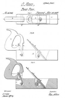
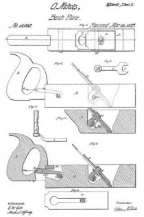
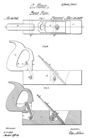
In explanation of the accompanying drawings and for reference thereto, Figure 1, denotes a plan or top view of the plane stock with the iron, and handle secured thereto, the handle being secured to the top of the plane. Fig. 2, denotes a side elevation of the same. Fig. 3, is a longitudinal and vertical section of it, on line A, B, Fig. 1. Fig. 4, is a plan of my plane with the handle attached, in its lowest position. Fig. 5, denotes a side elevation of the same. Fig. 6, is a longitudinal and vertical section of the same on line C, D, Fig. 4. Fig. 7 is a plan removed from the plane stock, of the cam shafts H and L, for holding both the plane iron and handle to the plane stock, and with the wrench for operating this cam, and for screwing the cap to the plane iron connected to, or placed on the cam shaft. Fig. 8, is a plan of this wrench. Fig. 9, denotes a plan of the plane iron C removed from the plane stock, with a section of the hook headed bolt E therein showing this bolt slabbed on each side to prevent turning when the cap D, is screwed to the iron C by the wrench I. Fig. 10, is a section of the plane stock A with a plate seen at gf intervening between the hook E and cam H.
Invention — The nature of my invention consists in firmly connecting the plane iron to the cap by means of a hook headed bolt and two nuts thereon, and the arrangement of a cam shaft to act on this hook by means of a wrench or its equivalent in such manner as to securely hold the plane iron to the stock, and the intermediation of a plate between the surface of the cam shaft and hook, which would otherwise come together to hold the plane iron to the stock, and the application of substantially the same arrangement to the handle whereby one handle will answer for any number of planes or molding tools, and the variable position of this handle which can be changed on the same, to be nearly as low as the face of the plane, to operate it with the greatest ease or in securing it to the top of the plane for planing floors or any desired work, all as hereinafter set forth.
Construction — To enable persons which are efficiently skilled in the art to which my invention appertains, to construct and carry out the same, I will describe it as follows:
I construct a plane stock as seen at A, in Figs. 1, 2, 3, 4, 5, 6, and 10, of the drawing, I then construct the plane iron seen at C Figs. 1, 2, 3, 4, 5, 6, 9, and 10, and the cap seen at D, same figures, and secure them together by a hook headed bolt seen at E Figs. 1, 2, 3, 6, 9 and 10, on which is placed two nuts, one top of the cap seen at F, Figs. 1, 3, 4, 6, and 10, and the other one under the plane iron seen at G Figs. 3, 6 and 10, these nuts are both properly threaded to the bolt E, the top one F, is to firmly hold the cap D to the iron C, and the lower one G, is to adjust the position of the surface or face a, Figs. 3, 6, and 10, of the hook headed bolt E, any desired distance from the iron C, in order to be in the proper position to be acted upon to hold the plane iron to the stock by the cam seen at H, Figs. 1, 2, 3, 4, 5, 6, 7, 3, and 10, which is fitted to the plane stock A, by first forming a hole therein for this cam shaft to freely turn in, the cam shaft H is constructed by turning an iron arbor round and smooth, and forming one of its ends square, on which to place the wrench I Figs. 7 and 8, so as to turn this cam shaft, to tighten and hold the iron to the stock by bringing the surface e, Figs. 3, 6, and 10, of this shaft H in contact with, and against the surface a, of the hook headed bolt E.
A portion of the cam shaft H, is removed leaving a vacant place seen at i, Figs. 3, 6, 7, and 10, so that by turning this cam shaft around so as to bring this vacant place i opposite or nearest the face a, of the hook E, the plane iron will be liberated so that it may be removed from the plane stock, for sharpening or any desired purpose.
It is designed to turn the cam shaft H, so as to bring its surface e, against the surface a, of the hook, in the position seen at Figs. 3, and 6, and 10, in order to hold the plane iron sufliciently firm to the plane stock, while this iron can be driven down to take a rank shaving, or driven up to take a lighter shaving as may be desired by the operator, without altering the tension of the iron to the plane stock.
A plan of the cam shaft H is shown in Fig. 7, disconnected from the plane stock, to better illustrate the part removed leaving a vacant place seen at i, for liberating the plane iron from the stock; an edge view of the wrench I, is also shown connected to this shaft H, in Fig. 7, and a plan of it is shown at Fig. 8, the large end J being fitted to turn either of the nuts F or G, for the purposes before stated i, e, for holding the cap D, to the plane iron C, and for adjusting the hook surface a, of the bolt, to be correctly operated upon by the cam shaft H, to hold the plane iron firmly to the stock.
At Fig. 10 is seen a plate g, held to the stock A, by the screw y, this plate intervenes between the surface e, of the cam shaft H, and the surface a, of the hook E, to prevent wear of these surfaces, and to prevent the plane iron from sliding, or moving when it is tightened to the stock. Single plane irons can be secured to the plane stock in precisely the same manner every way as the double iron; the hook headed bolt may be as much shorter for the single iron than it is in the double one, as the thickness of the cap D, which will be readily understood.
I construct one plane handle seen at B Figs. 1, 2, 3, 4, 5 and 6, so as to answer for a whole set of planes, or for any number of planes and molding tools by shaping its front edge as seen at n, and m Figs. Q, 3, 5 and 6, so that the surface n, of the handle B can be placed on the top or higher surface of the plane A, as seen at Figs. 2 and 3, the hook K Figs. 2 and 3, 5 and 6, swinging free on the pin , Figs. 3, 4, 5 and 6, in the slot P, Figs. 3 and 6, the surface k, of the hook K, is operated upon (after being placed in the mortise M) by the surface h, of the cam shaft L, to hold the plane handle firmly to the stock, by turning the cam shaft L with the same wrench I, that is used to operate the cam shaft H, and nuts F and G.
The elevated position of the plane handle is designed for using the plane to finish floors of vessels or buildings and for smoothing or finishing in corners or places diflicult of approach, the distance from the center of the pin Q, in the plane handle, to the center of the cam shaft L, in the plane stock is the same whether the handle is in the elevated or lower position.
The handle B, can be instantly removed from the plane stock A, Figs. 1, 2, and 3, or equally well from any molding tool stock by placing the wrench I upon the square part of the cam shaft L and turning it back so as to bring the vacant or open part j, of the cam shaft L, nearest to the surface k, of the hook K, when the handle will be liberated and it can then be placed in the lowest position as seen at Figs. 4, 5, and 6, by placing the hook K into the mortise N, and the surface k, so that it can be operated upon by the surface h, of the cam shaft L, to firmly hold the handle B, in the lowest position seen at Figs. 5 and 6, which is the best for the easy working of the plane, by reason of the hand of the operator being thus in the lowest position possible when operating the plane and of course the hand will thus operate the plane in nearly a direct line with its face. The advantages are very great in this changeability of handle on the same plane from a higher to a lower, or from a lower to a higher position to work the plane with the great-est ease, or for convenience in working the plane in low places, or unapproachable places for the body, while the arms and hands can reach to work the plane if the handle be secured to the stock in the elevated position as seen at Figs. 1, 2, and 3, and another important advantage is my arrangement, whereby the handle can be applied to any number of either planes or molding tools, or both, thus saving much expense in first constructing the tools, and then in packing them, besides the advantage of change of position of the handle on the same plane, as above stated.
Use — In using my invention of plane, the cap D, has first to be secured to the plane iron, if the iron be a double one, by the fork J, of the wrench I, applied to the nut F, then it is placed in the plane stock A, in position to cut in the usual manner, the cam shaft H being of course turned so that its recess i, is next the surface a, of the hook-headed bolt E, then this cam shaft H, is turned so as to bring the surface e against, and in contact with the surface a, of the hook E, which will firmly hold the plane iron to the stock. When the round surface e, of the cam shaft H, is brought in contact with the surface a, of the hook E, no farther pressure will be had, if the cam shaft H, be turned farther because this surface e, is the round part of the cam shaft H, and this arrangement will allow the operator to either set, or adjust the plane iron (to give the thickness of shaving) with a hammer, or with the cam shaft H and wrench I, as he may wish.
The plate g, Fig. 10, intervenes between the surface a, of the hook E, and the surface e, of the cam shaft H, and prevents wear, and also prevents the plane iron from sliding by the friction on the hook E, caused by turning the cam shaft against it to tighten the iron to the plane stock.
For using the plane or molding tool, upon bench work the lower position of handle, seen in Figs. 4, 5, and 6, is the desirable one, as the plane will work much easier by the hand of the operator at this low point of the plane, but if floors of vessels or buildings, or other like surfaces are to be planed which are low and more difficult of access than bench work, then the higher position of the handle is desirable, as seen in Figs. 1, 2 and 3. The change of handle from one position to another is effected simply by turning the cam shaft L, back with the wrench I, sufliciently to liberate the hook handle K, then remove this handle and place it in the lower position, with the hook K, so that the cam shaft L, can be turned by the wrench I to tighten the plane handle in the desired position.
What I claim, is —
1. Connecting the cap D, to the plane iron C, by the hook headed bolt E with two nuts F, and G, thereon to hold them together, and then securing the iron to the plane stock A, by a cam shaft H operating upon this same hook headed bolt, which is so adjustable as to be lengthened or shortened that any desired pressure may always be had, to firmly hold the iron to the stock, by turning the cam shaft, and still allow the plane iron to be moved in or out of the plane to cut a thick or thin shaving, without farther tightening or loosening it, these parts being arranged and operated essentially in the manner and for the purposes fully set forth.
2. I also claim the plate g, secured to the plane stock, and intervening between the surface a, of the hook E, and the surface e, of the cam shaft H, to prevent wear of the hook and cam, and also to prevent the hook E, and plane iron C from sliding back when the cam shaft H, is turned to tighten the iron to the plane stock, essentially in the manner and for the purposes fully set forth.
3. I also claim the application of one single handle B, to answer for, and be secured to a whole set or any number of plane stocks, either in the lower or elevated position, and changeable from one position to another or from one plane to another, instantly and be secured firmly thereto by means of the hook K, and cam L, or their mechanical equivalents arranged and operated essentially in the manner and for the purposes fully set forth.
OLDIN NICHOLS.
Witnesses:
JOHN S. JACQUES,
E. W. SCOTT.

