
No. 17,735 – Securing The Stock To The Guide Rods Of Joiner’s Plows (Stephen Going) (1857)
UNITED STATES PATENT OFFICE.
_________________
STEPHEN GOING, OF NEW YORK, N. Y.
DEVICE FOR SECURING THE STOCK TO THE GUIDE-RODS OF JOINERS’ PLOWS.
_________________
Specification of Letters Patent No. 17,735, dated July 7, 1857.
_________________
To all whom it may concern:
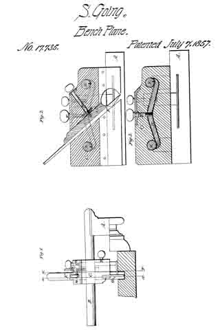
Be it known that I, STEPHEN GOING, of the city, county, and State of New York, have invented a new and Improved Plow for Joiners’ Use; and I do hereby declare that the following is a full, clear, and exact description of the same, reference being had to the accompanying drawings, making a part of this specification, in which —
Figure 1 is a front view of my improvement. Fig. 2 is a longitudinal vertical section ofthe same (x) (x) Fig. 1, indicating the plane of section. Fig. 3 is also a longitudinal vertical section of the same, (y) (y) Fig. 1, indicating the plane of section.
Similar letters of reference indicate corresponding parts in the several figures.
My invention consists in the peculiar mode of securing the stock on guide-rods which are attached to the gage.
The invention has for its object the ready adjustment of the stock on the guide rods.
To enable those skilled in the art to fully understand and construct my invention, I will proceed to describe it.
A represents the gage to which two parallel cylindrical rods B, B, are attached. The gage is of the usual construction, and the rods B, B, which are guide rods, are attached to the gage in the usual way.
The guide rods B, B, ass transversely through the stock C. This stock is constructed in the usual manner.
Within the stock C a metallic rod or bar D is placed. The bar D is fitted in a recess (a) in the stock, and the lower end of a screw E is fitted into the center of the bar D. The screw E passes vertically into the stock C, and the ends of the bar D have each a concave surface as shown at (b) Fig. 3, and these concave surfaces (b) are at the bottom of the circular openings through which the guide rods B, B, pass. The recess (a) in the stock is made sufficiently large to allow a certain degree of vertical play or movement to the bar D, so that when the bar D is forced down to the lower part of the recess (a) by turning the screw E, the stock will be allowed to work freely back and forth on the guide rods. And when the stock is to be secured on the rods the concave surfaces (b) are pressed or bound firmly up a ainst the rods B, so that the stock will be firmly clamped to them. By this means the stock C may be readily moved and secured at any desired point on the rods B, and the parallelism of the stock and gage will always be preserved.
F represents the iron which is fitted in an inclined mortise in the stock. This mortise is of slightly taper form longitudinally, and a wooden key G is litted therein.
H is a screw-rod, which asses obliquely into the stock C, and at right angles to the face of the iron F. The inner part of the screw rod passes through a nut (c) placed in the stock as shown in Fig. 2, and the inner end of the rod, which has a journal (d)
formed on it, is fitted in a recess in the key G.
It will be seen from the above description of parts that by merely turning the screw-rod H, the key G may be made to press tightly against the iron F and secure the same firmly in the mortise. And as the screw-rod H , passes into the key G at right angles to it tlhe back of the iron F will be pressed firmly against the back of the mortise, and the iron will thus be prevented from working loose in the mortise. The great advantage in this arrangement is the relative position of the screw-rod with the iron and key, namely, at right angles. If the screw-rod were laced obliquely with the iron F, the iron wouild be liable to work loose in the mortise.
The ordinary plows, at least those of the most approved kind, have their stocks rendered adjustable on their guide rods by having screw-threads formed on said rods, and nuts and followers fitted thereon. The objection to the most modern plow now in use is that considerable time is lost in adjusting the iron placed in said stock at any parallel line required. By my improvement the iron in said stock may be adjusted with the greatest facility and also at parallel lines at any point of said guide rods.
Having thus described my invention, what I claim as new and desire to secure by Letters Patent is:
Securing the stock C, on the guide-rods B, B, by means of the bar D, fitted within the stock and actuated by the screw E, substantially as and for the purpose set forth.
STEPHEN GOING.
Witnesses:
W. TUSCH,
J. F. BUCKLEY.