
| PLEASE NOTE: The images presented on this page are of low resolution and, as a result, will not print out very well. If you wish to have higher resolution files then you may purchase them for only $2.95 per patent by using the "Buy Now" button below. All purchases are via PayPal. These files have all been cleaned up and digitally enhanced and are therefore suitable for printing, publication or framing. Each zip package contains all the images below (some packages may contain more), and purchased files can be downloaded immediately. |

United States Patent Office.
NELSON PALMER OF AUBURN, NEW YORK, ASSIGNOR TO HIMSELF, SIDNEY W. PALMER, AND J. FOREMAN PALMER., OF SAME PLACE.
Letters Patent No. 64,790, dated May 14, 1867.
_________________
IMPROVEMENT IN BENCH-PLANES.
_________________
The Schedule referred to in these Letters Patent and making part of the same.
_________________
TO ALL WHOM IT MAY CONCERN:
Be it known that I, NELSON PALMER, of Auburn, in the county of Cayuga, and State of New York, have invented certain new and useful Improvements in Planes; and I hereby declare the following to be a full, clear, and exact description of the same, reference being had to the accompanying drawings.
My invention consists, first, in constructing an ordinary bench or other plane so that the throat or opening through which the bit projects shall be of variable size to suit the pitch of the bit and the nature of the work to be performed. In order to do this I make that part of the face of the plane in front of and bordering on the throat, adjustable or capable of being moved away from or toward the bit, according as it is desired to increase or diminish the distance between them. This arrangement is productive of important results, for the throat may be thereby so nearly closed as to cause the shaving-cut by the bit to be thrown up in an almost perpendicular direction, thus obviating the necessity of using, in connection with the bit, a cap, or, as it is sometimes called, “break-iron,” unless in exceptional cases, as, for instance, when the wood is very green and tough. In order to form a perfectly accurate bed for supporting the movable plate or section which regulates the size of the throat I resort to the expedient of running between it and the frame in which it is set, a backing of lead or other suitable material, which, when it hardens, will constitute an accurately-fitting bed supporting the plate at those points which determine its position in the face of the plane. I employ a similar expedient to form a perfect bed for the heel of the bit, as hereinafter described.
My invention farther consists in supporting the bit upon a movable bed, whose lower cud is pivoted or hinged to the frame or stock of the plane in rear of and close to the throat. The bed is capable of being depressed or elevated, its upper end moving in a circle, the centre of which is the point at which the bed is pivotcd to the stock. Its angle of inclination with respect to the throat may thus be varied at pleasure, and the bit which it supports may consequently be adjusted to any desired pitch.
Another feature of my invention is the construction and arrangement of the mechanisms for holding the bit in position on the bed, and for adjusting and maintaining it in and to its proper relations with the threat and face of the plane, i. e., for regulating its “cut” or the distance it shall project out from the throat, and for keeping or preserving its parallelism with the face of the plane. These various devices are all attached to and secured in the bed, and are actuated and operated in the manner hereinafter described.
My invention also consists in supporting the heel or lower part of the bit against a solid bed or backing of metal or other suitable material of suffiicient hardness, formed between it and the back of the throat. The object I have in view is to make a bearing or backing for the bit at the point where the strain mostly comes, when the plane is in use. By placing an accurately-fitting bed between the back of the throat and the heel I am enabled to accomplish this object. When the bit is secured in position on the movable bed, its lower end is pressed firmly and solidly against the backing, effectually checking and preventing any and all vibration ofthe bit, a defect to which ordinary planes are very liable, as is well known.
Lastly, my invention consists in the construction and arrangement of a detachable and independent cap or “break-iron” for turning or bending the shavings up out of the way, which may be secured to or removed from the bit with facility. It is further made adjustable by connecting the two pieces of which it is composed, by means of eccentrics, which may be operated by a lever or equivalent device, so as to adjust the blade or lower end of the cap in its proper position on the bit.
Having thus described the general features of my invention, I will now proceed to detail more particularly the manner in which it is or may be carried into effect by reference to the drawings, in which —
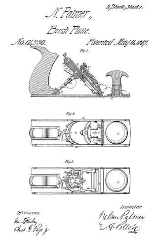
Figure 1 represents a longitudinal vertical section of a plane constructed in accordance with my invention;
Figure 2 is a plan view of the same.
Figure 3 is a like view with the cap and bit removed so as to show the construction and arrangement of the tilting or movable bed.
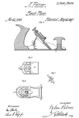
Figure 4 is a longitudinal vertical section of a plane in which a modification of my invention is shown; and
Figures 5, 6, and T are views of detached parts.
The mechanism for increasing and lessening the size of the throat consists of a movable and adjustable plate, C, which is placed in the front part of the plane, so as to be flush with and form part of the face. It is supported and held in proper position to the face of the plane by a backing or accurately-fitted bed of suitable material formed between it and the stock, as above explained. Just in rear of it is the slot or opening which constitutes the throat of the plane. The plate is capable of sliding longitudinally in the stock, its motion being limited and controlled by at stem, c, attached to its upper side, which extends up through at slot, g, formed in the top of the frame A. Upon the stem c is cut a screw-thread, so that it may engage with the hollow shank b: of the knob I, which is screwed down upon that part of the stem e projecting above the surface of the stock. It will be seen that the plate may thus be moved so as to close or open the throat, being held in any desired position by the shank b, which, when the plate is properly adjusted in relation to the hit, is screwed down tightly ever the male stem c, and maintains the whole device firmly in position. The plate is let into the stock, which thus forms in frame in which it is set so as to be flush with the surrounding face of the plane. The plane itself is what is known as a metallic plane, its stock or frame being cast iron. The movable or tilting bed G, which supports the bit, is pivoted or hinged at its lower end to the cast-iron stock a little in rear of the throat. Its pivotal points y’ constitute the axis upon which it is moved for the adjustment of the bit to its proper pitch.
As shown in the drawings, it consists of at skeleton frame which carries the mechanism for adjusting the bit, both as to the extent to which its cutting edge shall project from the throat, and as to its lateral inclination in order to maintain the parallelism of its edge with the face of the plane, and also for regulating its pitch and locking or fastening it in place. These different mechanisms I will now proceed to describe in detail:
First. The devices for adjusting the “cut” of the bit or its verticlal adjustment. The skeleton-frame G contains in its upper part an interior circular frame, G’, which is recessed so as to receive a, rotary disk, K. This disk is of somewhat less size than the recess, and has a groove formed in its periphery. The space between it and the annular frame G’ is filled with an anti-friction metal x, which enters the groove formed in the disk, and thus holds it in position, being itself retained in place by the V shape given the interior surface of the surrounding frame G’. Other methods, however, of holding the rotary disk K in its annular frame will readily suggest themselves, and nmy be used with perhaps equally good effect. The disk carries an eccentric-pin, y, to which is attached a plate, L, which extends downward some distance on the front of the bed, and has a. projecting tooth, i, formed on its face and, near its lower end. The tooth engages with an rack, h, attached to or formed on the under side of the bit B, and by this means, whatever movement is given the plate L, by reason of its eccentric connection with the rotary disk, is imparted to the bit. The toothed plate slides between guides m, which prevent it from moving in other than a longitudinal direction.
This mechanism operates in the following manner: When the bit B is in position on the bed G, and it is desired to adjust its cutting edge so that it shall project more or less from the face of the plane, the disk K is rotated by means of a lever-arm, E, rigidly connected therewith. This rotation of the disk causes, of course, a change in the position of the eccentric-pin y, which is raised or lowered according as the lever E is moved to the right or left. The movement of the pin y is communicated to its plate L, which is raised or lowered in a corresponding degree. The bit B is made to follow the motion of the toothed plate by means of the tooth i, which engages with the rack h, and draws with it the bit as it is moved up and down. Therefore, by simply moving the lever E or other equivalent device for rotating the disk, the bit may be set or adjusted vertically with great ease, and with perfect accuracy and nicety.
Second. The mechanism for adjusting the cutting edge of the bit, so as to maintain its parallelism with the face of the plane. About midway between the two ends of the bed G is it transverse sliding bar, D. This bar extends across the bed, in which are formed recesses or guides to receive it. It is capable of a sliding motion transverse to the length of the bed, and is held in place by the lower and smaller end m’ of the plate L which laps over and holds it against the bed. The end m’ lies between two jaws l l projecting from the face of the sliding bar, the distance between which is sufiicient to prevent their interference with the arm or plate L, when the bar D is moved to and fro. The jaws, when the bit is in place, embrace or grasp the rack h and draw it, and consequently the bit with them, when the bar to which they are attached slides in one direction or the other. In order to accommodate itself to this movement the bit is made capable of at little play between the sides of the stock, so that when its upper part is moved in either direction the lower end will be tilted or laterally inclined in a corresponding degree, and thus throw forward one side or the other of the cutting edge, as desired.
The transverse motion is given to the sliding ber D by providing it with at short arm or spur f, which extends back from the bar in such manner as to fit in a spiral or cam-groove, p, formed in the face of a shaft, k, which is supported in suitable bearings on the under side of the bed G. Upon one of the ends of this shaft a lever-arm, S, is secured by means of which the shaft may be rocked or rotated. When the lever S is moved up or down it will induce the rotation of the shaft, which in turn will, through the medium of the cam groove p and spur f, cause the bar D to slide from right to left, or vice versa, according as it is desired to advance one end or the other of the cutting edge of the bit. By this means the edge may be always kept parallel with the face of the plane, being adjusted to and in such position with the greatest accuracy and precision.
The bit and bed are locked or bound together and held in proper operative position by means of a toggle-jointed lever, H N. The lever N, which is nearest the bed, is forked at one end, fitting on the respective journals of the cam-shaft k. The other arm, II, of the lever terminates in a point, which fits in a corresponding cup or depression formed in the heed of a thumb-screw, P, which is secured to the handle of the plane so as to face the bed. A lever-handle, e, which extends upward from the arm H, is the means by which the lever is operated, and the joint either bent or straightened, as required. When the bit is placed on the bed, and it is desired to secure them in place, the lower end of the arm H is placed in the depression in the head of the thumb-screw P.
The lever e is then pressed forward, which causes the straightening of the toggle-joint, the other arm N of the lever forcing the bed and superincumbent bit up against pins a a, secured at the proper height in the sides of the stock. The bit and bed are thus held firmly between the straightened lever and the pins, which prevent their further motion in either direction. When the bit is to be removed, the toggle-joint must of course be bent by pressing back the lever e, after which the bed can be drawn down far enough to allow the bit to be withdrawn.
If, however, it is only desired to adjust the edge of the bit properly to the face of the plane, the bit need not be loosened. It may still be moved under the pins a a, which bind it down to the bed to a limited degree, by means of the levers S and E, which regulate its position with regard to the throat and face of the plane, as above explained. The pins a can be placed at any height in the stock to give the required pitch to the bit, and the thumb-screw P can be screwed in or out to adjust the bearing of the toggle-jointed lever. If a very steep pitch be required for the bit, as in a veneering or like plane, the lever H can be reversed so that its longer arm H’ may take its place and support the bed in a more elevated position.
To give an additional support to the heel of the bit I place between it and the rear of the throat a stationary bed, d, forming a, solid backing, against which the heel bears firmly, thus preventing the vibration of the bit when the plane is used. It is important that this backing should accurately fit the bit, and I have found that the best method of accomplishing this is to run between the heel and the back of the throat molten lead or other suitable metal, or any plastic material that will harden, so as to form at sufliciently firm and solid bearing for the heel of the bit.
In connection with the bit and bed thus constructed and arranged, I use it cap or “break-iron,” which is not attached to the bit, and which can be removed from or adjusted to the mouth of the plane with great facility. The cap is composed of two section or pieces F F’, as shown in the drawings. They are so placed in relation to each other that their contiguous edges overlap. The upper piece F’ is recessed so as to receive the projecting arm o of the lower section F. A rod or disk which binds the two parts of the cap together is inserted through the arm o, its other end being supported in a bracket or pending arm extending from the upper part of the piece F’. The two ends u v of this cylindrical disk are eccentric with respect to each other, and the disk itself, like the disk K above mentioned, is capable of being rotated by at lever, r, which projects through at segmental slot, s, in the upper piece F’. By means of this eccentric connection between the two plates F F’ I am enabled to move them toward or away from each other, as desired. The lower plate F has secured to it the blade or “break-iron” proper, M, which is held by screws w fitting in slots w’ formed in the lower portion of the piece F. The length ofthe blade M may thus be regulated. The cap, as will be seen by reference to the drawings, is placed on top of the bit. It is held in its proper relations to the edge of the bit and to the throat by means of a set-screw, t, in its upper end, which when screwed down will force the cap up until it meets the pins n, which like the pins a project from the side of the stock, and also fit in recesses formed in the upper plate F’ for their reception. The esp can thus be held firmly in place. Its accurate adjustment to the bit is effected through the medium ofthe lever r, which when moved will cause the lower part F of the cap to slide up or down, as it is required to increase or lessen the distance between its edge and the edge of the bit. As before said, by means of the movable plate C I am enabled to dispense with the use of a cap, unless when the wood is very green and tough; and for this reason, in feet, the cap is made so as to be easily attached to or removed from the plane.
My invention is capable of being modified in many particulars, as shown in fig. 4; for instance, where the movable bed G, unprovided in this case with the various mechanisms which I have just described, is supported and held in place by curved and slotted arms A’ A’, which overlap each other, one attached to the stock, the other to the bed, and both being held together by a set-screw passing through the slots, which, when loosened, allows the pitch of the bed to be adjusted, and when tightened holds the two arms together in my desired position. The bit may be either pressed against the bed by pins a a and levers, as shown in fig. 1, or it may be held in place by a set-screw, or by other suitable means. The defferent mechanisms which I have described may also be varied in memy respects without departing from the principle of my invention.
Having therefore described my invention, and the manner in which it is or may be carried into effect, what I claim, and desire to secure by Letters Patent, is —
1. The combination, with the movable section or plate for adjusting the size of the throat, of a recessed bed and frame formed in the plane-stock in front of the bit, and parallel to the face of the plane, so as to enclose the said section on three sides and form the ways in which it slides for purposes of adjustment, substantially as shown and set forth.
2. The bed for supporting the heel of the bit, formed of lead or other suitable plastic material, as specified, run between the said heel and the back of the throat, so as to form an accurately-fitting and solid bed for bit close to its cutting edge, substantially as herein set forth.
3. The method of and means herein described for adjusting the bit longitudinally, so that it shall project more or less from the face of the plane, that is to say, connecting the bit with an eccentric mounted in the bed of the bit, the eccentric being operated substantially as herein shown and set forth.
4. I claim the mechanism for maintaining the parallelism of the edge of the bit with the face of the plane, the same consisting of the combination, with the bit and bed in which it is supported, of a bar capable of sliding laterally in the bed, as described, and connected with the bit under such an arrangement that it shall cause the edge of the bit to be tilted or inclined toward one side or the other, substantially as set forth.
5. The combination of the transverse sliding bar, provided with jaws and projecting arm or spur, as described, with a cam or spiral grooved shaft and actuating lever or equivalent means, substantially as herein shown and set forth.
6. The combination, with the tilting or movable bed and bit which it supports, of the toggle-jointed and reversible lever, and holding-pins in the sides of the stock, substantially as herein shown and described.
7. The combination, with the movable bed and toggle-jointed lever, of an adjustable bearing for the said lever, substantially as set forth and described.
8. I claim the adjustable cap herein described, the some consisting of an upper and a lower plate or section connected by an eccentric rod or disk, whereby the lower section may be adjusted in its proper relation to the cutting edge of the bit, substantially as shown and set forth.
9. I claim the combination, with the movable section for adjusting the size of the throat, of the knob for securing the same under the arrangement herein described, so that the said knob shall not only serve to adjust and hold the said section in place, but shall also be a handle for guiding the movement of the plane, substantially as set forth.
In testimony whereof I have signed my name to this specification before two subscribing witnesses.
NELSON PALMER.
Witnesses :
HORACE T. COOK,
J. J. SHEPHERD.