
No. 165,355 – Improvement In Tonguing And Grooving Planes (Charles G. Miller) (1875)
UNITED STATES PATENT OFFICE.
_________________
CHARLES G. MILLER, OF NEW BRITAIN, CONNECTICUT, ASSIGNOR TO THE STANLEY RULE AND LEVEL COMPANY, OF SAME PLACE.
IMPROVEMENT IN TONGUING AND GROOVING PLANES.
_________________
Specification forming part of Letters Patent No. 165,355, dated July 6, 1875; application filed April 9, 1875.
_________________
To all whom it may concern:
Be it known that I, CHARLES G. MILLER, of New Britain, in the county of Hartford and State of Connecticut, have invented an Improvement in Tonguing and Grooving Planes, of which the following is a description and specification, reference being had to the accompanying drawings, where —
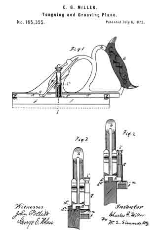
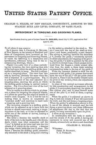
Figure 1 is a side view of a plane embodying my invention, the view showing that side of the tool upon which the shifting guide, hereinafter described, is hung. The tool is adjusted as a tonguing-plane. The view from this side is, however, precisely the same when the tool is adjusted as a grooving-plane. Fig. 2 is a front-end view of the tool adjusted as a tonguing-plane, showing the pivot, on which the shifting guide is hung, in central vertical section. Fig. 3 is a front-end view of the tool adjusted as a grooving-plane.
This invention is a device which is, at pleasure, a plane for tonguing the edges of boards, or a plane for grooving the edges cf boards to receive such tongues. It is a tool for use in making what is known to carpenters as “matched stuff,” and combines in itself both a tonguing and a grooving tool.
The invention consists in a shifting guide, which can be adjusted so as to leave both the knives or chisels uncovered, making a tonguing-plane of the tool; or it can be adjusted to cover one of the chisels or knives, making a grooving-plane.
The letter a denotes the metallic stock or body of the tool; b, the handle, and c the throat, down which runs what carpenters call the “iron” d, forked at its lower end into the two chisels d1 d2, which do the cutting. e denotes the wedge which holds the iron in place. The letter f denotes the shifting guide, eccentrically attached to the shaft i, hung and rotating in the socket g, attached to the stock a. The pin i1 runs into the top of the shaft or trunnion i, and forms, practically, a part thereof. The spring m, bearing between the shoulders g1 i2, presses the guide f constantly upward. In either adjustment, for tonguing or for grooving, the guide f is held to position by the pins n, (shown in dotted lines,) which project downward from the fingers o, which project side-wise from the stock a, three teats entering corresponding holes in the top of the guide f.
When the operator desires to shift the adjustment of the guide f, he presses downward upon the top of the pin i1 till the guide clears the pins n, when it can be readily rotated upon its pivot in the socket g from one adjustment to the other.
In place of the vertical movement allowed, by this construction and arrangement, to the guide f, I contemplate depriving the guide of this vertical play, and in place thereof make one of the pins n, or both of them, a spring-catch.
When the guide f is adjusted as shown in Fig. 2, both the chisels d1 d2 are left uncovered for work, and the tool forms a tonguing-plane. When the guide f is adjusted as shown in Fig. 3, one of the chisels is covered, and the tool forms a grooving-plane; and these differences of adjustment are due to the fact that the guide f is hung eccentrically upon its pivot.
I claim as my invention —
ln combination with the body or stock a and the chisels d1 d2, the guide f, having adjustments to cover and uncover one of the chisels, substantially as shown and described.
CHARLES G. MILLER.
Witnesses:
FRED. N. STANLEY,
T. A. CONKLIN.