No. 405,540 – Plane (John J. Driver) (1889)
[paiddownloads id=”450″]405540


UNITED STATES PATENT OFFICE.

_________________

JOHN J. DRIVER, OF ST. LOUIS, MISSOURI.

PLANE.

_________________

SPECIFICATION forming part of Letters Patent No. 405,540, dated June 18, 18589.
Application filed December 5, 1888. Serial No. 292,703. (No model.)

_________________

To all whom it may concern:

Be it known that I, JOHN J. DRIVER, a citizen of the United States, residing at St. Louis, in the State of Missouri, have invented certain new and useful Improvements in Planes, of which the following is such a full, clear, and exact description as will enable any one skilled in the art to which it appertains to make and use the same, reference being had to the accompanying drawings, forming part of this specification.

My invention relates to handles for planes, whereby the same can be manipulated by persons when standing to plane floors and the like, obviating the necessity of getting down on the knees.

The invention consists in features and details of construction which will new be set forth at length, and then particularly pointed out in the claims making a part hereof.

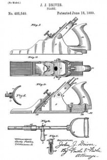
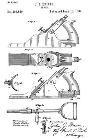
Figure 1 is a side elevation of a plane having my handle applied thereto. Fig. 2 is a plan view of the same. Fig. 3 is a longitudinal sectional view of the same. Fig. 4 is a view showing the handle only. Fig. 5 is a section on the line 5 5 of Fig. 4. Fig. 6 is a section of a detail.

The same figures of reference indicate the same parts throughout the various views.

5 is the plane, whichis of any ordinary construction and preferably made of metal.

6 is the cutter-blade, which is adjusted in said plane by any ordinary means. This means makes no part of my invention. I entend the metal sides of the plane to form ears 7 at each side of said plane, and to these ears 7, I journal my handle by a bolt 8, which passes through said handle and said ears.

The handle is preferably made of a bow-shaped piece 9, which has a screw-threaded socket 10 at its top and middle. This screw-threaded socket receives, preferably, a rod or pipe 11, screw-threaded at both ends, of any desired length, which may be joined to a second piece of pipe 12 to form the handle. The pipes or rods 11 and 12 are joined together by a nut 13, having a right and left hand screw-thread, so that when the nut is screwed down the ends of the rods 11 and 12 are brought together and make a tight joint. To the pipe 12 is swiveled at the point 13′ a handle 14, so that said handle 14 may be turned at any angle. Upon the pipe or rod 12 is also a second handle 15, which is made so as to be adjustable along said rod to accommodate the person using the plane. This handle 15 is made up of a screw-threaded bolt 16, which passes through the wooden part 15 of the handle, and has an eye 18 for receiving the rod 12. By screwing the wooden part 15 in one or the other direction it can be made to approach or recede from the rod 12, and thus allow said handle to be moved along said rod or fastened securely to the same at any point. The handle 14 is for one hand of the user and the handle 15 for the other hand. The ears 7 are about midway between the cutting-line 19 and the heel 20 of the plane, in order that the handle maybe attached to the plane at a point midway between 19 and 20, so as to equalize the pressure at the point 19 and the point 20.

If the handle were attached to the plane farther back, too much pressure would be thrown upon the heel 20 of the plane and too little pressure put upon the cutting-line 19. So, too, if the handle were attached farther forward of the plane too much pressure would be applied along the cutting-line.

The bolt 8 can be readily removed when it is desired to take the handle off of the plane and use it as an ordinary plane. Said handle can be made of any length by joining together any number of sections 11 and 12.

By the means described floors and other objects can be planed by persons when standing as readily as when upon the knees and with much less fatigue.

The invention is simple and effective, the construction strong and of small cost.

21 is the ordinary handle of the plane, which is fastened to said plane by screws 22 and 23, and may be removed from the plane, if in the way, when the other handle is attached.

Having fully set forth my invention, what I desire to claim and secure by Letters Patent of the United States as my invention is —

1. A handle for planes, consisting of the bow-shaped part 9, having screw-threaded socket 10, one or more screw-threaded rods joined to the same, a handle 14, swiveled to the upper end of said rods, and a handle 15, adjustably secured along said rods, for the purpose described.

2. The combination, with a plane, as herein set forth, of the ears 7, a bow-shaped piece 9, swiveled to said ears 7 by a bolt 8, screw-threaded socket 10 upon said bow-shaped piece, screw-threaded rod 11, adapted to be inserted in said socket 10, a second screw-threaded rod 12, a nut 13, having right and left hand screw-threads thereon for joining the rods 11 and 12 together, a handle 14, swiveled to said rod 12, and a handle 15, adjustable along said rod 12, substantially as and for the purpose described.

In testimony whereof I have hereunto set my hand and affixed iny seal, this 3d day of December, 1888, in the presence of the two subscribing witnesses.

JOHN J. DRIVER. [L. S.]

Witnesses:
A. C. FOWLER,
W. S. REEDER.

No. 381,186 – Plane (Reinhard T. Torkelson And Iver Johnson) (1888)

[paiddownloads id=”435″]381186


UNITED STATES PATENT OFFICE.

_________________

REINHARD T. TORKELSON AND IVER JOHNSON, OF WORCESTER, MASSACHUSETTS.

PLANE.

_________________

SPECIFICATION forming part of Letters Patent No. 381,186, dated April 17, 1888.
Application filed September 14, 1885. Serial No. 177,099. (No model.)

_________________

To all whom it may concern:

Be it known that we, REINHARD T. TORKELSON and IVER JOHNSON, both of the city and county of Worcester, and Commonwealth of Massachusetts, have invented certain new and useful Improvements in Planes; and we do hereby declare that the following is a full, clear, and exact description of the same, reference being had to the accompanying drawings, forming a part of this specification, in which —

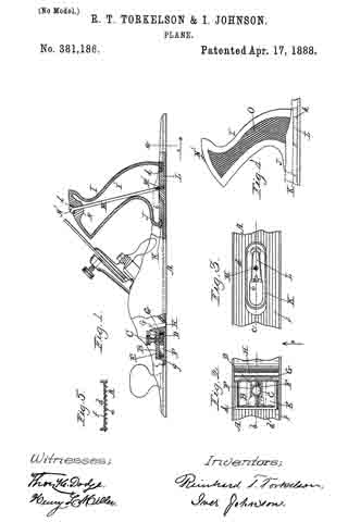
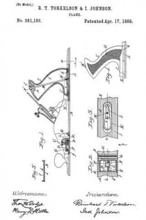
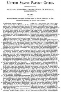
Figure 1 represents a vertical section through the ends of the plane on line b c, Figs. 2 and 3; Fig. 2, a top or plan view of the front of the plane; Fig. 3, a top or plan view of the rear section of the plane with the handle removed; Fig. 4, a side view of the handle and a small section of the plane-bed; and Fig. 5 represents a cross-section on line a, Fig. 1, looking in the direction of arrow 1.

To enable those skilled in the art to which our invention belongs to make and use the same, we will proceed to describe it more in detail, the nature of which consists, first, in certain improvements in the construction of an adjustable throat device; second, in improvements in the construction, whereby the handle may be detachably fastened to the bed; and, third, in an improved plane-bed, all as will be hereinafter more fully described.

In the drawings, A represents the bed of the plane,which is provided with corrugations d, the lower edges, e, of which are flat, and upon its upper side with round corrugations f. By this construction of the bed it can be made very light, while at the same time it is very stiff, thus utilizing in material, while at the same time rendering it light, and thus requiring less labor to operate it.

B represents an adjustable throat arranged upon the upper side of the plane-bed, through which a thumb-screw, C, passes into a set-nut, D. This nut works between two dovetail flanges, F F, (shown in full lines, Fig. 1, and dotted lines, Fig. 2,) the sides of the nut being made dovetailing to fit, and, consequently, while the nut can be moved back and forth it cannot be raised out of place until screw C and throat B are removed.

The body part E of the adjustable throat rests upon upright flanges g, (shown in full lines, Fig. 1, and dotted lines, Fig. 2,) and between the side flanges ofthe plane-bed F F. A forward projection, G, fits into the throat H, and which projection can be slid back and forth, as indicated in full and dotted lines, Fig. 1, and quickly adjusted, by means of the thumb-screw G, to give any desired opening to the throat H. This arrangement also leaves the under side of the bed of the plane smooth, thereby obviating the objections to the adjustable throats heretofore fitted to work on the under side of the plane.

I represents the handle of the plane, made of vulcanized india-rubber. It is made hollow, as seen at I’, and with a rounded base, J, to fit into a socket-piece, K, which in turn is made with an oblong slot, i, having edges inclined toward each other, so that said socket-piece K may be placed over the dovetail projection L on bed A, and when forced forward into the position shown in Fig. 1 it is securely held in said position vertically under the beveled edges k of said projection L. The base of handle I is now placed in the socket-piece K, and the screw-rod M passed down through the top and screwed into hole M’ in the dovetail projection L, thereby securing the handle firmly in position, while at the same time admitting of the detachment of said handle in an easy and expeditious manner. A forward projection, N, is cast upon the under side of the top of the handle, as fully indicated in Fig. 1, and a metal socket-piece, Z, is ntted into the top of handle I, to receive and hold the head N’ of the screw-rod M. The sides of the handle are made with a series of notches or corrugations, O, whereby when the handle is clasped in the hand the soft skin and flesh of the fingers will be pressed into the corrugations and notches on one side of the handle, while the skin and soft flesh of the hand at the base of the fingers will be pressed into the corrugations upon the opposite side of the handle. By this arrangement the operator can handle the plane much easier and with less exertion, particularly when he is obliged to hold up the plane to plane the edge of a piece of board, which is frequently required in the usual work of a carpenter. If the handle were smooth, a little perspiration or oil would require a great strain upon the fingers and cords of the hand to hold the plane from turning; but with the corrugations as made upon the sides of said handle the difficulty is obviated. If preferred, the socket-piece K may be cast with the bed of the plane and dovetail projections omitted.

We are aware that planes with adjustable throats have been used before, and we do not therefore claim said device, broadly.

Having described our improvements in planes, what we claim therein as new, and desire to secure by Letters Patent, is —

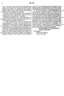
1. The combination of bed A, having the rear projection, L, upon the top thereof provided with the dovetail or bevel edges k, substantially as described, with the detachable socket-piece K, provided with an oblong vertical slot, i, having edges inclined toward each other, and adapted to be placed over said projection L, then forced forward and held vertically under the beveled edges k aforesaid, handle I, fitted at the bottom in said socket-piece K, and fastening-rod M, passed longitudinally through said handle and into bed A, substantially as and for the purpose set forth.

2. In a bench-plane, a throat-adjusting device located above the bed A in front of the throat H, consisting of said bed having the dovetail flanges F F and supporting-flanges g, in combination with the slide B, arranged over said flanges, and having the projection G next to said throat, the nut D, fitted to slide longitudinally over the bed between the dovetail flanges F F aforesaid, the latter holding said nut and slide B in position vertically, and thumb-screw C, fitted to turn in suitable vertical openings in the slide and nut, substantially as and for the purpose set forth.

REINHARD T. TORKELSON.
IVER JOHNSON.

Witnesses:
THOS. H. DODGE,
H. L. MILLER.

No. 379,346 – Plane (John J. Tower) (1888)

[paiddownloads id=”431″]379346


UNITED STATES PATENT OFFICE.

_________________

JOHN J. TOWER, OF BROOKLYN, NEW YORK.

PLANE.

_________________

SPECIFICATION forming part of Letters Patent No. 379,346, dated March 13, 1888.
Application filed November 1, 1886. Serial No. 217,674. (No model.)

_________________

To all whom it may concern:

Be it known that I, JOHN J. TOWER, of Brooklyn, in the county of Kings and State of New York, have invented an Irnprovement in Planes, of which the following is a specification.

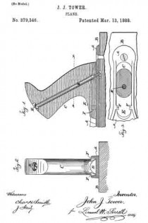
Bench planes are extensively manufactured with wooden handles fastened into a metal plate that is screwed upon the wooden body of the plane, and this plate extends forward of the handle and is provided with vertical flanges, between which the plane-iron is received. Difficulty has heretofore been experienced in attaching the handle in such a manner that the same will not work loose when in use and so that the handle can be disconnected with facility for packing or be rapidly and firmly replaced. I make use of a screw passing through the handle at an inclination to the plane, so as to strengthen the handle, and this screw enters the iron plate so as to clamp the handle thereto, and the bottom portion of the handle is extended forward and passes in between undercut lugs upon the iron plate, so that the weight of the plane when it is lifted by the handle is partially taken upon the undercut lugs, and any tendency to bend the screw is prevented and the thrust upon the handle when the plane is in use is received jointly by the clamping-screw and the undercut lugs.

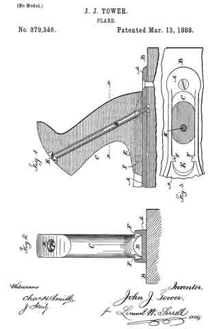
In the drawings, Figure 1 is a section through the handle and part of the iron plate. Fig. 2 is a cross-section of the plate and an elevavation of the handle; and Fig. 3 is a sectional plan below the line x x, Fig. 1.

The plate A is usually of iron and provided with side flanges, between which the plane-iron is received, and my improvement is available with planes having a face formed of the iron plate; but l have shown the said iron plate as fastened to a wooden base, B, forming the face of the plane.

The handle C is of wood or similar material and of the desired shape for being grasped by the hand. The long part of the handle is extended forward, as at E, and its edges are inclined inwardly.

Upon the plate A are straight parallel flanges having the lugs F, which are in a position adjacent to the forward part of the base of the handle. These lugs are undercut or dovetailed, which can be most conveniently effected by a rotary cutter, so that the inner faces of the lugs correspond to the inclined sides of the bottom and forward part of the handle, and the handle is to be slipped in between the straight parallel flanges, and the forward end passes below the said lugs.

There is a hole passing through the handle in a position diagonal to the plate A, and the screw H, having a countersunk head, is passed through this handle into a threaded hole in the plate A. By this means I am able to firmly attach the handle to the plate and to allow for removing the handle with facility for packing the plane or for replacing the handle when desired for use, and the handle is not weakened by any dovetailed grooves on its edges.

In cases where a screw has been passed through the handle the weight and leverage of the plane tend to bend the screw, and when dovetailed ribs on the iron plate have received the edges of the handle such edges have been grooved on a bevel and the handle weakened, and there is nothing to prevent the handle drawing back out from the ribs.

By my improvement the lugs F only pass over the forward lower end of the handle, but they effectually hold this end from lifting and with the screw form a strong and reliable attachrnent.

If a screw were passed through the forward lower end of the handle, it would not hold the parts as strongly and reliably as the dovetail lugs.

I claim as my invention —

The combination, with the plane-handle and the screw passing through the sarne, of a metal plate into which the screw passes, and which plate has straight parallel flanges for receiving between them the lower part of the handle, and the lugs F, that come over the forward beveled end of the base of the handle, substantially as set forth.

Signed by me this 26th day of October, 1886.

JOHN J. TOWER.

Witnesses:
GEO. T. PINCKNEY,
WILLIAM G. MOTT.

No. 180,867 – Improvement In Bench-Planes (Jackson Gorham) (1876)

[paiddownloads id=”266″]180867


UNITED STATES PATENT OFFICE.

_________________

JACKSON GORHAM, OF CRAWFORDVILLE, GEORGIA, ASSIGNOR TO HIMSELF AND CHARLES E. SMITH, OF SAME PLACE.

IMPROVEMENT IN BENCH-PLANES.

_________________

Specification forming part of Letters Patent No. 180,867, dated August 8, 1876; application filed July 11, 1876.

_________________

To all whom it may concern:

Be it known that I, JACKSON GORHAM, of Crawfordville, in the county of Taliaferro and State of Georgia, have invented an Improvement in Bench-Planes, of which the following is a specification:

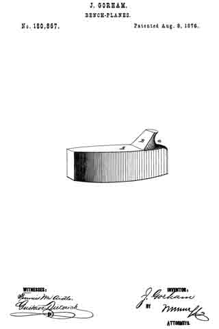
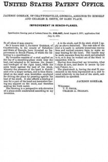
My invention consists of a stud applied on the top of a smoothing-plane stock near the heel, and adapted to fit between the thumb and forefinger of the right hand, while the palm bears against the heel of the stock, whereby the pressure of the hand is distributed over a larger surface, and is thus diminished on the small area heretofore employed for driving the plane by pressing against the heel of the stock. It also affords a bearing or rest for a part of the hand not heretofore having any support on the stock, and therefore making the work easier.

The drawing is a perspective side elevation of a plane-stock constructed according to my invention.

A is the stock, and B the stud, which I apply as above described. The rear side of the stud a is made in suitable transverse convex; form and vertical concave form, to make an easy bearing for the hand. The handle may be made separate from the stock and attached to it, or it may be worked out of the block in connection with it.

Having thus described my invention, what I claim as new, and desire to secure by Letters Patent, is —

The plane-stock A, having the stud B, constructed in the form represented at a, and located relatively to the heel of the stock, substantially as specified.

JACKSON GORHAM.

Witnesses:
V. T. SMITH,
CHARLES A. BEAZLEY.

No. 179,494 – Improvement In Bench-Planes (John J. Tower) (1876)

[paiddownloads id=”264″]179494


UNITED STATES PATENT OFFICE.

_________________

JOHN J. TOWER, OF BROOKLYN, NEW YORK.

IMPROVEMENT IN BENCH-PLANES.

_________________

Specification forming part of Letters Patent No. 179,494, dated July 4, 1876; application filed May 29, 1876.

_________________

To all whom it may concern:

Be it known that I, JOHN J. TOWER, of Brooklyn, in the county of Kings and State of New York, have invented an Improvement in Metal Plane-Handles, of which the following is a specification:

Metal planes have heretofore been constructed with handles of wood, and also with globular knobs at the forward end of the plane.

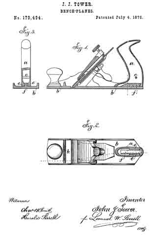
My improvement relates to a hollow cast-metal handle, secured to the plane by dove-tailed projections, so that the connection is very strong and durable, and at the same time the handle is very light, and of a size and shape to be grasped by the hand.

The handle is represented in the drawing by a vertical seetion, Figure 1, horizontal section, Fig. 2, and cross-section, Fig. 3.

The handle a is of cast metal, preferably of iron. It is made hollow, so as to be as light as possible and maintain the requisite strength. The general shape of this handle is similar to those made of wood, and hence it is as convenient in use. In order to strengthen the lower part of the handle, and prevent the same being bent by the attachment to the plate b of the plane, I introduce the cross-bar c, cast with the rest of the handle. Dovetails that taper slightly are employed for fastening the base of the handle to the plane-stock. These dovetails are made by lips inside the base of the handle, as seen at e. The dove-tail block f upon the plane-stock b is shorter than the base of the plane-handle a, and the dovetail portions e do not extend the whole distance along the inner edges of the handle, so that the handle a can be put over the dove-tail-block f by slipping it from the back forward, and keeping the back edge down, in order that the handle may receive the dove-tail-block, and the parts tapering, the handle may be secured firmly by driving it forward upon the dovetail block. By this construction it is not necessary to have any opening at the forward part of the base of the handle, as such base sets down flat upon the plane-stock, and makes a neat, handsome, and durable connection, the dovetail not being visible.

This hollow cast-iron plane-handle may be plated or otherwise finished, and as the handle extends to the upper surface of the bottom of the plane, the hand of the operator can be as near to the surface of the wood as possible, so that the power can be exerted to good advantage.

I do not claim a plane with a hollow knob or handle with dovetail projections for holding the plane-iron to the stock, as this has been used; neither do I claim a hollow metal plane-handle.

I claim as my invention —

The metallic plane-handle cast hollow, with a cross-bar, c, and dovetail lips e extending a part of the distance along the inner portion of the base, in combination with the dovetail block f upon the stock of the plane, substantially as set forth.

Signed by me this 22d day of May, A. D. 1876.

JOHN J. TOWER.

Witnesses:
GEO. T. PINCKNEY,
CHAS. H. SMITH.

No. 157,069 – Improvement In Plane-Handles (Frank Goodnow) (1874)

[paiddownloads id=”233″]157069


UNITED STATES PATENT OFFICE.

_________________

FRANK GOODNOW, OF ALBION, NEW YORK.

IMPROVEMENT IN PLANE-HANDLES.

_________________

Specification forming part of Letters Patent No. 157,069, dated November 24, 1874; application filed October 9, 1874.

_________________

To all whom it may concern:

Be it known that I, FRANK GOODNOW, of Albion, in the county of Orleans and State of New York, have invented certain Improvements in Plane-Handles, of which the following is a specification:

My invention consists in the combination of a plane-handle with devices which render it readily attachable and detachable to the plane, so that one handle may be used on any number of planes.

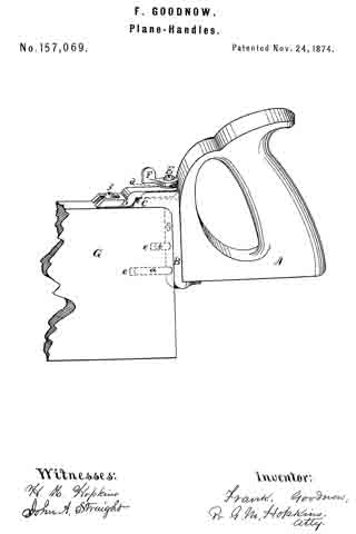
In the accompanying drawing, which is a perspective view, A is a handle of any ordinary form. B is a strap, which is secured to it by means of screws or otherwise, and is provided with the dowels a and b, and also a support at C, for the slotted cap-plate D. The slotted cap-plate D has its fulcrum at c, and is provided with a cam-shaped projection, d. E is a screw, which passes loosely through the slotted cap-plate D into the strap B. On this screw a short lever, F, is placed, which is provided with a cam, which engage with the cam-shaped projection d on the slotted cap-plate D. Two holes, e e, are made in the end of the plane G, corresponding with the dowels a and b. A screw is placed in the top of the plane at f in such a position as to engage with the slotted cap-plate D, which is slotted to receive it.

The handle, having been previously fitted to the plane, is attached to it by passing the dowels into the holes in the end of the plane, and at the same time passing the slotted end of the slotted cap-plate D under the screw f The lever F is now turned; this depresses the end of the slotted cap-plate D, and consequently raises the slotted end, causing it to bear with sufficient force against the under side of the head of the screw f to hold the handle firmly to the plane.

Having thus described my invention, what I claim as new, and desire to secure by Letters Patent, is —

The combination of the handle A, strap B, provided with the support C and dowels a b, slotted cap-plate D, provided with a cam-shaped projection upon its rear end, cam-lever F, and plane G, provided with holes e e, constructed substantially as shown and described.

FRANK GOODNOW.

Witnesses:
GEO. P. HOPKINS,
JOHN A. STRAIGHT.