No. 144,823 – Improvement In Metallic Planes (Joseph F. Baldwin) (1873)

[paiddownloads id=”220″]144823


UNITED STATES PATENT OFFICE.

_________________

JOSEPH F. BALDWIN, OF BOSTON, ASSIGNOR TO JOHN SULLY, TRUSTEE, OF DEDHAM, MASSACHUSETTS.

IMPROVEMENT IN METALLIC PLANES.

_________________

Specification forming part of Letters Patent No. 144,823, dated November 25, 1873; application filed June 7, 1873.

_________________

To all whom it may concern:

Be it known that I, JOSEPH F. BALDWIN, of Boston, in the county of Suffolk and State of Massachusetts, have invented certain Improvements in Metallic Planes, of which the following is a specification:

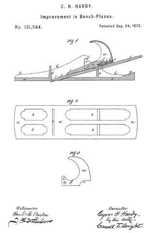
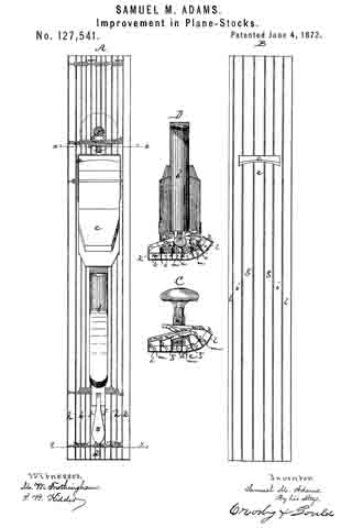
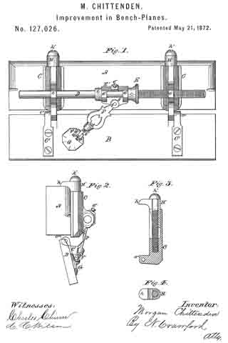
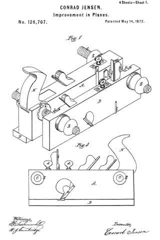
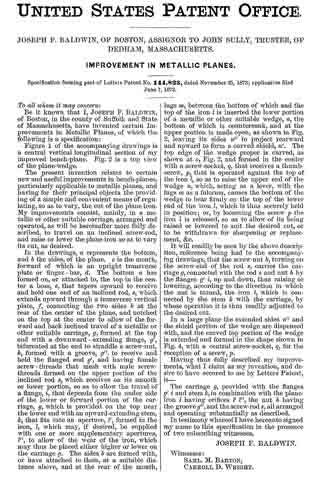
Figure 1 of the accompanying drawings is a central vertical longitudinal section of my improved bench-plane. Fig. 2 is a top view of the plane-wedge.

The present invention relates to certain new and useful improvements in bench-planes, particularly applicable to metallic planes, and having for their principal objects the providing of a simple and convenient means of regulating, so as to vary, the cut of the plan-iron. My improvements consist, mainly, in a metallic or other suitable carriage, arranged and operated, as will be hereinafter more fully described, to travel on an inclined screw-rod, and raise or lower the plane-iron so as to vary its cut, as desired.

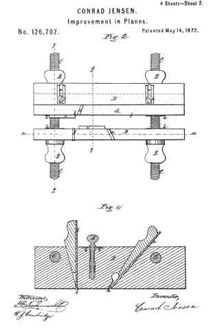
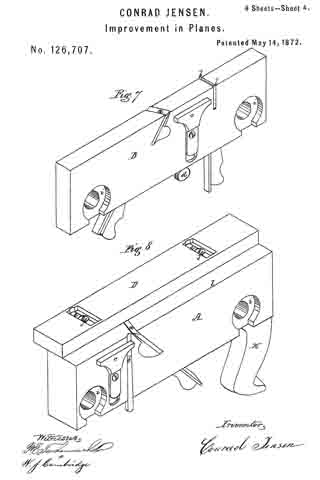
In the drawings, a represents the bottom, and b the sides, of the plane. c is the mouth, forward of which is an upright transverse plate or finger -bar, d. The bottom a has formed on, or attached to, the top in the center a boss, e, that tapers upward to receive and hold one end of an inclined rod, s, which extends upward through a transverse vertical plate, f connecting the two sides b at the rear of the center of the plane, and notched on the top at the center to allow of the forward and back inclined travel of a metallic or other suitable carriage, g, formed at the top end with a downward-extending flange, g’, bifurcated at the end to straddle a screw-nut, h, formed with a groove, g”, to receive and hold the flanged end g’, and having female screw-threads that mesh with male screw-threads formed on the upper portion of the inclined rod s, which receives on its smooth or lower portion, so as to allow the travel of a flange, i, that depends from the under side of the lower or forward portion of the carriage, g, which is provided on the top near the lower end with an upward-extending stem, k, that fits into an aperture, l’, formed in the iron, l, which may, if desired, be supplied with one or more supplementary apertures, l”, to allow of the wear of the iron, which may thus be placed either higher or lower on the carriage g. The sides b are formed with, or have attached to them, at a suitable distance above, and at the rear of the mouth, lugs m, between the bottom of which and the top of the iron l is inserted the lower portion of a metallic or other suitable wedge, n, the bottom of which is countersunk, and at the upper portion is made open, as shown in Fig. 2, leaving its sides n” to project rearward and upward to form a curved shield, n’. The top edge of the wedge proper is curved, as shown at o, Fig. 2, and formed in the center with a screw-socket, q, that receives a thumb-screw, p, that is operated against the top of the iron l, so as to raise the upper end of the wedge n, which, acting as a lever, with the lugs m as a fulcrum, causes the bottom of the wedge to bear firmly on the top of the lower end of the iron l, which is thus securely held in position; or, by loosening the screw p the iron l is released, so as to allow of its being raised or lowered to suit the desired cut, or to be withdrawn for sharpening or replacement, &c.

It will readily be seen by the above description, reference being had to the accompanying drawings, that the screw-nut h, turning on the screw-end of the rod s, carries the carriage g, connected with the rod s and nut h by the flanges g’ i, up and down, thus raising or lowering, according to the direction in which the nut is turned, the iron l, which is connected by the stem k with the carriage, by whose operation it is thus readily adjusted to the desired cut.

In a large plane the extended sides n” and the shield portion of the wedge are dispensed with, and the curved top portion of the wedge is extended and formed in the shape shown in Fig. 4, with a central screw-socket, q, for the reception of a screw, p.

Having thus fully described my improvements, what I claim as my invention, and desire to have secured to me by Letters Patent, is —

The carriage g, provided with the flanges g’ i and stem k, in combination with the plane-iron l having orifices l’ l”, the nut h having the groove g”, and the screw-rod s, all arranged and operating substantially as described.

In testimony whereof I have hereunto signed my name to this specification in the presence of two subscribing witnesses.

JOSEPH F. BALDWIN.

Witnesses:
SAML. M. BARTON,
CARROLL D. WRIGHT.

No. 145,106 – Improvement In Bench-Planes (George W. Huber And Aaron E. Flickinger) (1873)

[paiddownloads id=”221″]145106


UNITED STATES PATENT OFFICE.

_________________

GEORGE W. HUBER AND AARON E. FLICKINGER, OF NORWALK, OHIO.

IMPROVEMENT IN BENCH-PLANES.

_________________

Specification forming part of Letters Patent No. 145,106, dated December 2, 1873; application filed October 18, 1873.

_________________

To all whom it may concern:

Be it known that we, GEORGE W. HUBER and AARON E. FLICKINGER, of Norwalk, in the county of Huron and State of Ohio, have invented a new and Improved Plane, of which the following is a specification:

In the accompanying drawing, Figure 1 represents a vertical longitudinal section of our improved plane; and Fig. 2, a vertical transverse section of the same on the line c c, Fig. 1.

Similar letters of reference indicate corresponding parts.

The object of our invention is to construct an improved plane, which is light, handy, and easily adjustable to any thickness of shaving without the use of a hammer. Our invention consists in the firm mounting of the plane-iron between a cap-piece with connecting clamping-bolt and set-screw, and a supporting-shoe, which is pivoted to the sides of the base-piece, and adiusted, together with the plane-iron, by a conical eccentric pivoted to the base.

In the drawing, P represents the base-piece of the plane, provided with front and rear handles H, and made preferably of cast-iron. The shoe B is pivoted at a to the side flanges of base A, and supports on its inclined front part the plane-iron D, while the backward-extending bracket-shaped sides rest with their broader ends on rubber cushions b, by which a certain degree of spring action is imparted to shoe B, so as to offer a yielding support to the plane-iron. The face part of shoe B is provided with a recess, d, and extension-slot e, for giving play to the screw-head d’ of the plane-iron D and clamping-bolt f of the cap-piece A. The plane-iron D has a perforation, f’, for the passage of bolt f. A conical eccentric, C, is pivoted to a lug, g, of base P, under the lower extremity of shoe B, and produced under the same inclination of its sides as the front part of shoe B, so as to raise or lower shoe B, as the eccentric C is turned, by means of its handle C’. The plane-iron is thus raised or lowered with shoe B, and the thickness of the planing regulated thereby. The slot through which the plane-iron projects is widened on lowering the iron, so that the thicker shavings may freely pass through the same; while, in raising the iron, the slot is narrowed in proportion to the thinner shavings, and thus the tearing up of the wood or the veneers prevented, and a neat and smooth surface produced. The cap-piece A is placed on the top of the plane-iron D, its clamp-bolt f passing through the slotted part of the iron and into slot e of shoe B. The sides of bolt f are recessed to correspond exactly to the width of slot e, while its broad head projects over the sides of slots e, and holding thereby the plane-iron and shoe in position. By means of a set-screw, h, at the upper end of cap A, the shoe B may be firmly tightened on the iron D, clamping it rigidly between cap A and shoe B. The plane iron is in this manner easily and firmly set into the plane, and readily adjusted to any degree of planing in a neat and convenient manner, economizing time, and forming a compact and strong implement for the trade.

Having thus described our invention, we claim as new and desire to secure by Letters Patent —

The improved adjustable plane, consisting of base-piece P, pivoted shoe B with rubber cushions b, conical eccentrics C C’, perforated plane-iron D, and clamping cap~piece A, constructed substantially as and for the purpose as described.

GEORGE W. HUBER.
AARON E. FLICKINGER.

Witnesses:
E. R. JACKSON,
T. H. KELLOGG.

No. 129,508 – Improvement In Planes (Levi A. Alexander) (1872)

[paiddownloads id=”200″]129508


UNITED STATES PATENT OFFICE.

_________________

LEVI A. ALEXANDER, OF PITTSFIELD, MASSACHUSETTS.

IMPROVEMENT IN PLANES.

_________________

Specification forming part of Letters Patent No. 129,508, dated July 16, 1872.

_________________

To all whom it may concern:

Be it known that I, LEVI A. ALEXANDER, of Pittsfield, in the county of Berkshire and State of Massachusetts, have invented an Improvement in Planes, of which the following is a specification, reference being had to the accompanying drawing.

My invention consists in providing an edging-plane with an adjustable hinged guide by which the plane may be regulated so as to cut or plane the edge of the wood at any desired angle.

Figure 1 is a side view of a plane having my guide applied, and Fig. 2 an end view of the same.

A represents the plane, constructed in the ordinary manner, and B a long bar provided with arms at which are screwed to the side of the plane so as to hold the bar in place along its lower edge. In each end of the bar B there is mounted a transverse slide, C, and a thumb-screw, D, for fastening the same; and to the inner ends of these slides is hinged the guide E, consisting simply of a flat plate or bar. The guide, thus arranged, can be turned so as to present its face at any desired angle to that of the plane; and, to provide for holding it in the required position, it is provided with a curved arm, F, passing through a stud, c, on the bar B, and the stud provided with a thumb-screw, G, which may be set up against the curved arm so as to hold it firmly. To facilitate the adjustment of the guide at any particular angle, the curved arm F is provided with graduations properly numbered, so that it is only necessary to turn the guide until the proper graduation on the arm is brought in line with the stud c, and then to turn up the thumb-screw so as to fasten the arm. The guide may also be adjusted laterally on the face of the plane by loosening and moving the slides C.

In using the plane it is applied so that the face of the guide bears flatly against the side or face of the wood, so as to hold the face of the plane at the desired angle to the edge of the wood, as shown in Fig. 2, so that, upon operating the plane. it cuts the edge of the wood down to the exact bevel or inclination desired. The guide may, of course, be adjusted so as to cause the plane to cut the edge at a right angle to the face, instead of beveling.

By the use of the guide the trouble of constantly testing and fitting the edge by a hand-gauge in the usual manner is avoided and a perfectly true and even edge produced. The guide may be readily applied to any ordinary plane, and can be quickly removed when necessary.

Having described myinvention, what I claim is —

A guide for planes consisting of a plate, E, hinged by adjustable arms C to the bar B, the latter being provided with the arms a, with the graduated quadrant F, and the means for securing the same in place, all constructed and arranged to be applied to a plane, substantially as and for the purpose set forth.

LEVI A. ALEXANDER.

Witnesses:
LORENZO H. GAMWELL,
ELISABETH ALEXANDER.

No. 145,311 – Improvement In Plane-Irons (Ernest Quast) (1873)

[paiddownloads id=”222″]145311


UNITED STATES PATENT OFFICE.

_________________

ERNEST QUAST, OF JERSEYVILLE, ILLINOIS.

IMPROVEMENT IN PLANE-IRONS.

_________________

Specification forming part of Letters Patent No. 145,311, dated December 9, 1873; application filed February 18, 1873.

_________________

To all whom it may concern:

Be it known that I, ERNEST QUAST, of Jerseyville, in the county of Jersey and State of Illinois, have invented a new Improvement in Plane-Irons; and I do hereby declare that the following is a full and exact description of the same, reierence being had to the accompanying drawings, and to the letters of reference marked thereon.

This invention is a plane-bit having a shank of cast malleable iron, or common wrought-iron, and a removable cutting-edge of steel, the same constituting a new article of manufacture, as will be fully described hereafter.

In the drawing the plane-bit is shown in perspective.

A represents the upper section of the bit, of the usual form, and is made of iron, preferbly cast malleable iron. B is the cutting-part, made of suitable cast-steel. C is a screw or rivet, by which the parts are held together. a a’ are overlapping tongues, shaped to engage with each other, so as to form a scarf-joint of the two parts A and B. It will be seen that where the two parts A and B butt together at d and d’, the edge d is square, while d’ is beveled. Both may, however, be beveled, if so preferred.

When the steel part B is worn out, it can be quickly and easily removed by taking out the screw or rivet C. The part A, in consequence of being subject to but little wear, may thus be made to serve for almost an unlimited number of steel bits. It therefore follows that these plane-bits constructed as described, possess all the advantages of those made entirely of steel, and can be produced as cheaply as those made of steel and iron welded together, without that deterioration in the quality of the steel which is almost inseparable irom the process of welding.

Having fully described my invention, what I claim as new, and desire to secure by Letters Patent, is —

The plane-bit described, having the iron shank A and steel cutting-part B, as a new article of manufacture.

This specification signed and witnessed this 5th day of February, 1873.

ERNEST QUAST.

Witnesses:
JAMES A. LOCKE,
DENNIS BROWN.

No. 146,004 – Improvement In Combination-Planes (Andrew Johnson) (1873)

[paiddownloads id=”223″]146004


UNITED STATES PATENT OFFICE.

_________________

ANDREW JOHNSON, OF SAN FRANCISCO, CALIFORNIA.

IMPROVEMENT IN COMBINATION-PLANES.

_________________

Specification forming part of Letters Patent No. 146,004, dated December 30, 1873; application filed November 15,1873.

_________________

To all whom it may concern:

Be it known that I, ANDREW JOHNSON, of San Francisco city and county, State of California, have invented a Combination-Plane; and I do hereby declare the following description and accompanying drawings are sufficient to enable any person skilled in the art or science to which it most nearly appertains to make and use my said invention without further invention or experiment.

The object of my invention is to provide an improved combination-plane, the novelty of which consists, mainly, in the use of a series of adjustable guides and gages by which the tool may be made to out in straight lines or upon the concave or convex surfaces of the work, whether such surfaces lie in the line of the tool or at right angles with it. My invention further relates to the employment of a series of cutting-irons which may be so combined as to cut any desired form of molding.

Referring to the accompanying drawings for a more complete explanation of my invention, Figure 1, Sheet 1, is a perspective view of my plane. Fig. 2 is a side elevation. Fig. 3, Sheet 2, is a back view. Fig. 4, Sheet 2, is a sectional elevation. Figs. 5 and 6 are detailed views of the gage.

A is the body of the plane or the block, and it is made short, so as to facilitate its use on short curves. From its lower face project the plates B, one in front and one behind the cutter, and which serve as a guide for the plow and as a back for the cutting-iron. These plates are secured by set-screws, C, which pass horizontally through slots in them and enter the projecting lower part of the block A. The plates are so formed that a thin elastic strip of metal, c, extends on each from near the cutter forward and backward respectively to the front and rear of the block, where they are turned up and have a horizontal portion, d, which is slotted to receive a set-screw, e, which secures it to the vertically-adiusting standard I. A wide open space intervenes between the part B of the plates and the strip c. The strip unites with the plate at the end nearest the cutters, but is free at the opposite end, so that it can be adjusted up and down when the tool is to be used upon concave or convex surfaces in a vertical plane.

If the tool is to be used around concave or convex surfaces which lie in a horizontal plane, the set-screws e are loosened, and the elastic strip c is curved either to or from the block, as the case may be, and secured by the screws.

The guide and gage for this work consist of a plate, F, which has its center riveted to a projection, G, on the bar H, while its ends are connected with the ends of the bar by slotted links V, so that this plate F can be bent from side to side to correspond with the curve given to the strip c, and secured by set-screws, as shown. The bar H has a vertical post, J, extending upward, and this post is slotted to receive a set-screw, K, which secures it to the bar L. This bar L is connected at each end to the block A by long screws M, which have double nuts N N, between which the bar L is held, or smooth bars may be used instead of screws M with a set-screw. By means of these nuts the distance of the guide-plate F from the tool is regulated, while its vertical adjustment is made by means of the screw K and the slotted standard or post J.

In order to cut a variety of moldings with the same tool, I provide a number of cutters, n, of various shapes. The cutters have any suitable number of supporting-backs o, which have screws p passing through them, and provided with double nuts, so that the back plates can be adjusted to suit the number or kind of cutters. These plates and their equivalent guides o’ before the cutters may be cut away, as shown, so as to allow the tool to work freely on curves, either vertical or horizontal, and can be adjusted by the nuts to the highest point of the cutting-iron from the main face-plate. The lower ends of the cutters are supported by the back plates, and the upper ends are suitably connected with the setting-screw, so that any number of cutters can be easily adjusted at any time. In the present case I have shown a plate, R, which slides upon the inclined front of the handle s. This plate has two projections or lugs, t t, near its lower end, and upon these projections the holes or slots in the upper ends of the cutters are fitted. By the variation allowed by the slots each iron can be set separately. The plate B has a nut, x, formed at its upper end, and a screw, y, passes through this nut, and serves to operate the plate and move it up or down, as may be desired, to give the cutters the proper set. The cutters being placed, their upper ends will be held as described by the lugs t, while the lower ends are steadied by the back plates o. A plate, z, is fitted to press the cutters against these plates o, being operated by a screw, g, and this holds them firmly to their work, and causes them all to work as one tool. Gages h h, with set-screws, serve to regulate the depth of cut to be made, and the distance of the cut from any particular point or surface is regulated by means of the sliding bars m. The spring-gage can be adjusted up or down to facilitate the working of a molding upon the edge of a raised panel or a flat or plain surface.

It will be manifest that any number of wooden faces, Q, with either hollows, round, or flat surfaces can be made to fit the various combinations of cutters, and which may be substituted for or placed between the plates o, if desired, for straight work. The plate B, together with the blocks or faces Q, when used in place of the metal plates, serve to form a match-plane, the irons n, being employed with them.

Having thus described my invention, what I claim, and desire to secure by Letters Patent, is —

1. The plates B, having elastic adjustable curving strip c, combined with the block A and adjusting-standards I, substantially as and for the purpose described.

2. The combination of the elastic gage-plate F, bar H, and slotted links V with their set-screws.

3. In combination with the elastic adjustable gage-plate F, the vertically-sliding post J with its holding-screw, and the bar L with its horizontally-adjusting screws M, and the nuts N, substantially as and for the purpose herein described.

4. The adjustable curved plates o o’, in combination with plate B and intermediate blocks Q, substantially as and for the purpose set forth.

In Witness whereof I hereunto set my hand and seal.

ANDREW JOHNSON.

Witnesses:
GEO. H. STRONG,
C. MILTON RICHARDSON.

No. 129,695 – Improvement In Bench-Planes (Thomas Vaughan) (1872)

[paiddownloads id=”201″]129695


UNITED STATES PATENT OFFICE.

_________________

THOMAS VAUGHAN, OF BOSTON, MASSACHUSETTS.

IMPROVEMENT IN BENCH-PLANES.

_________________

Specification forming part of Letters Patent No. 129,695, dated July 23, 1872.

_________________

Specification describing certain Improvements in Bench-Planes, invented by THOMAS VAUGHAN, of Boston, in the county of Suffolk and State of Massachusetts.

My invention relates to a metallic shoe, into which the wooden body of the plane is fitted and secured by means of cement, said shoe being strengthened by ribs before and behind the cutter, and having grooves or flutings cut in various places upon its inner sides to hold the cement.

In the accompanying drawing, Figure 1 is a plan of the shoe, showing its shape, &c. Fig. 2 is a longitudinal section of the same, the shape and position of the plane being shown by dotted lines.

Similar letters of reference indicate corresponding parts.

a is the bottom of the shoe. a’ a’ are the sides and ends. In is the rib in front of the cutter. c is the rib behind the cutter. d is the opening for the cutter. e e e are flutings or grooves in the sides a’ a’.

This shoe is made of malleable cast-iron, and the body of the plane is cut away so as to fit into the shoe. The plane is secured therein by means of prepared cement, the flutings e e being for the purpose of more thoroughly fastening it, the cement filling into them. The ribs b c are intended to strengthen the shoe, and are very important, as it would without them be very liable to break when meeting with a fall from a considerable height. The casting throughout is of uniform thickness, (probably one~eighth of an inch ,) which gives the plane good proportionate weight. In planes made with my shoe I shall construct the cutter of gaged or uniform thickness throughout, so that the opening d shall retain its size and appearance as the cutter wears off. The cutter will also be secured by a wedge in the ordinary way. My plane (having the shoe) will “clean up” the hardest veneer without requiring a scraper, a few rubs with sand-paper being sufficient for any wood requiring the best French polish even.

A plane made as above-described, and having my shoe, costs about one-half as much as planes now in the market and purporting to do similar work. The wear is, of course, unlimited. The general shape of my shoe may be altered, of course, to fit different planes, such as block-planes; but the other features of the invention will be substantially unaltered.

I do not claim as my invention an iron or entirely metallic plane, but my shoe, in which is set a wooden plane, constructed as above described.

Having thus fully described , my invention, what I claim, and desire to secure by Letters Patent, is —

The combination and arrangement of tl shoe and sides and ends thereof a a’, ribs b c, and flutings e e, substantially as above described, and for the purposes hereinbefore set forth.

THOMAS VAUGHAN.

Witnesses:
HENRY W. WILLIAMS,
E. H. OBER.

No. 131,959 – Improvement In Match-Planes (Charles E. Marshall) (1872)

[paiddownloads id=”203″]131959


UNITED STATES PATENT OFFICE.

_________________

CHARLES E. MARSHALL, OF BOSTON, MASSACHUSETTS.

IMPROVEMENT IN MATCH-PLANES.

_________________

Specification forming part of Letters Patent No. 131,959, dated October 8, 1872.

_________________

To all whom it may concern:

Be it known that I, CHARLES E. MARSHALL, of Boston, in the county of Suffolk, in the State of Massachusetts, have invented certain Improvements in Match-Planes; and do hereby declare that the following description, taken in connection with the accompanying drawing, hereinafter referred to, forms a full and exact specification of the same, wherein I have set forth the nature of my said improvement, by which my invention may be distinguished from others of a similar class, together with such parts as I claim and desire to secure by Letters Patent.

My invention relates to that class of wood-working implements made use of for cutting grooves and tongues, commonly known as matching-planes; and the nature thereof consists in certain modifications and improvements in the details of the construction of the same, hereinafter described and shown.

In the accompanying plate of drawing, which illustrates my invention and forms a part of the specification thereof, corresponding parts are illustrated by similar letters.

Figure 1 is a view of the implement in perspective. Fig. 2 illustrates the position of the curvilinear projection or support for the left hand. Fig.3 is a detached view of the clamping apparatus.

The construction and operation of my invention are as follows: In the drawing referred to, letter A designates the tonguing, and B the grooving, edge, either of which may be used at will by merely reversing the direction of the plane — that is to say, when the tonguing-edge is used the right hand is applied to the handle C, and when the grooving-edge is made use of the right hand seizes the handle C’. The curvilinear projection D may be used with equal facility as a rest for the left hand, whichever edge is made use of. The diagonal support F of the blades H and I forms an angle of forty-five degrees with the edges of the plane, and is cast solid therewith. The blades or cutters are held in position by the clamps K K’, which are pivoted to the frame and operated by the thumb-screws L L’, as is clearly shown in Fig. 3.

Having thus described my invention, I will state what I claim and desire to secure by Letters Patent in the following clause — that is to say, I claim —

1. A reversible plane, provided with handles and a curvilinear rest, as described, so arranged that either edge of the plane may be operated with equal facility.

2. In a reversible plane, the combination of the diagonal rest, the cutters, and the clamps, all operating together, as and for the purposes described.

In witness whereof, I have subscribed my name hereto this 18th day of May, 1872.

CHARLES E. MARSHALL.

Witnesses;
TIMOTHY F. BOWE,
JOHN WATERS.

No. 133,162 – Improvement In Bench-Planes (Jacob Lehner) (1872)

[paiddownloads id=”204″]133162


UNITED STATES PATENT OFFICE.

_________________

JACOB LEHNER, OF GALENA, ILLINOIS.

IMPROVEMENT IN BENCH-PLANES.

_________________

Specification forming part of Letters Patent No. 133,162, dated November 19, 1872.

_________________

To all whom it may concern:

Be it known that I, JACOB LEHNER, of Galena, in the county of Jo Daviess and State of Illinois, have invented a new and useiul Improvement in Bench-Planes, of which the following is a specification:

My invention consists of a combination of screw-rods, nuts, and an adjusting-bar, with the plane stock and bit, in such manner that the setting of the plane-bit is effected by turning the nuts on the screw-rods, the latter being attached to the plane-stock at each side parallel with the bit. My invention also consists of a combination of a tightening-rod with the wedge and plane-bit for securing and releasing the latter; the said rod passing from the heel of the plane-stock through the plane-bit and its cap, which are slotted at the center for the purpose, into the wedge, in which it screws, and the plane-bit having two other slots, one at each side of the center slot, for the screws, by which the cap is secured to it, to allow the tightening-rod to pass through the center slot.

Figure 1 is a longitudinal sectional elevation through my improved plane on the line x x of Fig. 2, and Fig. 2 is a section on the line y y of Fig. 1.

Similar letters of reference indicate corresponding parts.

A is the plane-bit; B, the cap; C, the wedge; D, the screw-rods; E, the cross-bar; and F, the adjusting-nuts. The said rods are attached to the plane-stock, one at each side of the plane-bit, parallel with it, and extend a little higher than the bit does; the cross-bar fits on the rod above the plane-bit, so as to force it down by the adjusting-nuts F, which screw on the rods above the bar, two being used on each rod to fasten one by the other. G is the tightening-rod for fastening the bit and wedge; it passes from the heel of the stock, where it is provided with a thumb-bit for turning it, through the stock to the throat, and through the plane-bit and cap into the wedge, in which it screws. To allow this rod to pass through the center slot K of the plane-bit, a slot, L, is made on each side of it for the screws, by which the cap B is fastened to the bit.

It will be readily seen that the bit may be set and adjusted more accurately and nicely by this apparatus than by the common way of striking it with a hammer; that it cannot be forced back by the work, even though the wedge may not be as tight as necessary; and that the tightening of the latter can be effected better than by driving it in the common way, and the splitting of the stock common to that way of tightening it is avoided.

I am aware ofthe patent granted to J. K. P. Smith on the 9th of May, 1871, (and beg leave to disclaim the same,) but esteem my mode of combining means for holding and adjusting the bit as much simpler and more reliable than those shown by him.

Having thus described my invention, I claim as new and desire to secure by Letters Patent —

The rods D D, cross-bar E, nuts F, and tightener G, combined with wedge, cap, stock, and bit, as described, for the purpose of adjusting and holding the bit at any desired point in the stock.

JACOB LEHNER.

Witnesses:
JOHN McHUGH,
JOSEPH METZGER.

No. 133,632 – Improvement In Carpenters’ Plane-Irons (Albert N. Cross) (1872)

[paiddownloads id=”205″]133632


UNITED STATES PATENT OFFICE.

_________________

ALBERT N. CROSS, OF NECEDAH, WISCONSIN.

IMPROVEMENT IN CARPENTERS’ PLANE-IRONS.

_________________

Specification forming part of Letters Patent No. 133,632, dated December 3, 1872.

_________________

To all whom it may concern:

Be it known that I, ALBERT N. CROSS, of Necedah, in the county of Juneau and State of Wisconsin, have invented certain new and useful Improvements in Carpenters’ Plane-Irons; and I do hereby declare that the following is a full, clear, and enact description thereof, that will enable others skilled in the art to which it appertains to make and use the same, reference being had to the accompanying drawing and to the letters of reference marked thereon which form a part of this specification.

The nature of my invention consists in a cap and case used with a plane-iron, and so constructed that the cap can be set or adjusted at any distance from the edge of the blade, and the two together raised or lowered in the case, as will be hereinafter more fully set forth.

In order to enable others skilled in the art to which my invention appertains to maize and use the same, I will now proceed to describe its construction and operation, referring to the annexed drawing, in which —

Figure 1 is a plan view, Fig. 2 a side view, and Fig. 3 a longitudinal section, of my invention.

A represents the plane iron or blade, B the cap, and C the case. The case C is in the center, on the front, provided with two slots, a and b, the slot a, extending from the upper edge downward for a suitable distance, and at the lower end of said slot is formed a projection, d, on the outside of the case. Below this projection d is the slot b, running on the same line with the former slot. The blade A is also slotted, as shown in Fig. 3, and is, with the cap B, placed in the case. A screw, e, is then passed through the slot b of the case and through the slot in the blade, and screwed into the cap B, thus securing the blade and cap firmly together. By means of the slot in the blade the cap may be set at any desired distance from the edge of the blade to do good work. On the front side of the blade A, at or near the upper end, is a short post or projection, f the outer end of which has a hole with female-screw threads. Through this is passed a thumb~screw, D, the lower end of which goes loosely through the projection d on the case, and has a nut on its end to prevent its being withdrawn. By means of this thumb-screw D the blade is raised or lowered at will for thin or thick shavings, and, the cap being fastened to the blade, the two are of course adjusted at the same time.

The case C is to be wedged in the stock so as to be firm in the same, the whole forming a very convenient and useful improvement in planes.

Having thus fully described my invention, what I claim as new, and desire to secure by Letters Patent, is —

The within-described plane-iron, consisting of the slotted blade A, cap B, and slotted case C, the blade and cap being adjusted together by the set-screw e placed within the case and operated by the thumb-screw D, in the manner and for the purposes herein set forth.

In testimony that I clairn the foregoing I have hereunto set my hand.

ALBERT N. CROSS.

Witnesses:
E. S. MINER,
B. F. BUCK, JR.

No. 135,046 – Improvement In Molding-Planes (Alexander S. Robertson) (1873)

[paiddownloads id=”206″]135046


UNITED STATES PATENT OFFICE.

_________________

ALEXANDER S. ROBERTSON, OF BOSTON , MASSACHUSETTS, ASSIGNOR OF
ONE-THIRD HIS RIGHT TO JOHN M. BEALS OF SAME PLACE.

IMPROVEMENT IN MOLDING-PLANES.

_________________

Specification forming part of Letters Patent No. 135,046, dated January 21, 1873.

_________________

To all whom it may concern:

Be it known that I, ALEXANDER S. ROBERTSON, of Boston, in the county of Suffolk and State of Massachusetts, have invented certain new and useful Improvements in Molding-Planes for Carpenters’ and Joiners’ use, of which the following is a specification:

As bead-molding tools are now constructed it is necessary to have a separate tool for every desired size of bead-molding, making it necessary for the workman to have some ten or twelve tools of this kind. These several tools occupy quite a large space in a carpenter’s tool-chest, and add considerably to the cost of his kit.

The object of my invention is the production of a single tool which can accomplish all that the ten or a dozen now in use can do, and also which can be used successfully to stick bead-moldings on a curved surface, and be worked either right or left handed. My invention consists in the use of adjustable cylindrical cutters, or cutters having a rounded under surface, set in the side of a suitable stock in such a manner that the side of the stock shall serve as a gage or guide, one of said cutters being so formed as to out the quirk and one-half the circular surface of the bead, while another cutter cuts the other half of the circular surface of the bead, the first-mentioned cutter being so applied to the stock that it may be adjusted so as to project a greater or a less distance fromthe face or side of the stock. It also consists in providing said stock with two handles facing in opposite directions, and also in providing said stock with a cutter or cutters on either side thereof of different sizes, so that a greater range of work may be accomplished with one instrument, and also so as to accommodate either a right or left handed person.

In the drawing, Figure 1 is an elevation of my improved tool; Fig. 2 is a plan; Fig. 3 is a vertical transverse section on line x x on Fig. 2; Fig. 4 is a vertical transverse section on line y y; and Fig. 5 is a corresponding section on line z z on Figs. 1 and 2.

A is the stock, provided with the handles A’ and A”. B B are plates of sheet metal secured to the sides of the stock to prevent an injurious wear of the stock, and also to serve as an additional support for the cutters. C and C’ are the principal cutters, shaped very much like an ordinary wood-screw, except that the under side of the head is curved to conform to the shape of the bead instead of being conical like the screw, the slot being cut somewhat deeper than the screw-slot and expanded somewhat to give a free delivery to the chips. These cutters may be provided with a screw-thread and be screwed into the stock, as shown in Fig. 3 at C, or they may have smooth shanks and be secured in the stock in any desired position by means of the set-screw a, as seen in Fig. 5 at C’. For ordinary common work the cutters C and C’ are all that would be needed, the outer corner of the board or piece of lumber being rounded of by the use of a common plane, as is the custom when using the ordinary tool; but if a nicer job is desired a second cutter, D, may be used in combination with either ofthe cutters C or C’, the cutter D being so formed and adjusted as to work off and smooth the outer portion of the bead. The cutter D is secured in the stock by means of the set-screw b. The cutter-bar D may be provided with a cutter at either end, the form and size of the two cutters being made to match the respective cutters C and C’. The cutter C is intended to work beads from one-twelfth of an inch to one-fourth of an inch, and the cutter C’ will work from one-fourth of an inch to one-half of an inch; and for larger sizes an extra cutter will be provided, which can readily be inserted in the place of C’. Owing to the cylindrical form of the cutters and the narrow bearing which they have upon the wood, this tool will work as well upon a curved surface as upon a straight surface.

It is evident that a cutter that is semi-cylindrical, or having a curved under surface, may be used instead of the screw-cutter or the complete cylinder; and therefore I do not wish to confine myself to the exact form of cutter shown.

What I claim as new, and desire to secure by Letters Patent of the United States, is —

1. The cutters C and C’, constructed, arranged, and operating as herein set forth and described, for the purpose specified.

2. In combination with the cutter C or C’, arranged and operating as set forth, the cutter constructed and arranged substantially shown as described.

Executed at Boston this 27th day of August, 1872.

ALEXANDER SMITH ROBERTSON

Witnesses:
S. A. WOOD,
H. E. LOMBARD.

No. 131,544 – Improvement In Bench-Planes (Cyrus H. Hardy) (1872)

[paiddownloads id=”202″]131544


UNITED STATES PATENT OFFICE.

_________________

CYRUS H. HARDY, OF BOSTON, MASSACHUSETTS, ASSIGNOR TO JOSEPH F.
BALDWIN, MELINA C. PATTON, AND JOHN LULLY, OF SAME PLACE.

IMPROVEMENT IN BENCH-PLANES.

_________________

Specification forming part of Letters Patent No. 131,544, dated September 24, 1872.

_________________

To all whom it may concern:

Be it known that I, CYRUS H. HARDY, of Boston, in the county of Suffolk and State of Massachusetts, have invented certain Improvements in Metallic Planes, of which the following is a specification:

Figure 1 of the drawing is a central longitudinal vertical section, Fig. 2 is a bottom view, and Fig. 3 is a part in detail, of my improved metallic planes.

The object of my invention is to provide means for the ready adjustment of the blade of a plane; and it consists in so forming an adjustable shield, in connection with a wedge-block and sides of the plane-frame, to allow a blade to be readily adjusted in or withdrawn from the frame.

In the drawing, a represents the bottom of a frame of a metallic plane, the weight of which is diminished by the formation of openings or slots b, which may be of any form or size, arranged as may be desired, and either left open or filled with wood or other light material or substance. The bottom a is provided with a suitable mouth, c, and has extending across, transversely, and upward a suitable distance, a finger-bar or rest, d, of any desired form. Toward the rear end of the frame is a vertical transverse bar or standard, e, extending upward to the height required to give the proper angle to a blade, f, the bottom of which rests upon it, and whose edge is formed by an upward bevel, f’. The rear end of the bottom a, is formed with a striking-block, g. Extending up from the bottom a are curved sides h, sloping upward toward the center of the plane, where each is cut away so as to leave on the top a projection, i, curved on the under side to admit the turning of an upward-curved portion or cam, k, formed by the forward part of projecting ends of the bottom of a shield, m, which is curved at the sides, back, and top, as shown in Figs. 1 and 3, and has its bottom cut away, as at n, to fit over the top of the blade f and is formed with a bottom frame or plate, o, provided with bearings o’, in which a bolt, p, having a suitable spring, p’, and thumb piece p” , is made to travel back and forth, in and out of a socket, x, formed in the end of a beveled or wedged block, r, formed to it within the curved front of the frame or plate o and the projecting sides l, to the latter of which it is attached by pivots s, or other suitable means, for allowing the shield on to turn over the top of the block r, the bottom of which rests upon the blade f, which is held by the pressure of the wedge-block r and cam k upon it.

Reference being had to Figs. 1-3 of the drawing, it will be seen that, by unlocking the bolt p from the block r, the shield m is, by the action of the cams k and pivot s or its equivalent, allowed to turn over the top of the block r, which is, by the operation, carried up, and lessens its hold on the blade f, which may then be easily withdrawn or adjusted in the desired manner. When the blade f is inserted in the position required the bolt p is unlocked from the wedge-block r, the shield m is turned by the action of the cam k onto the blade f which is securely held by the wedge-block r and cam k, and forms a guard that serves as a support to the hand, the fingers of which find a hold on the forward rest or bar d. The principal function of the spring-bolt p is to prevent the liability of the tipping of the cam is or the forward projections l of the shield m when power is applied to the upper part of the back of the shield. Instead of the bolt p and spring p’, &c., a spring-clutch, or any other suitable device for holding and relieving the wedge-block r, may be used.

It will readily be seen that by my improvements the blade f is inserted at a low angle, which admits of its being readily withdrawn or adjusted, and permits the shield m, which serves as the handle, to be placed near the mouth and center of the plane, and thus prevents the rising of the forward part of the plane, which is often liable to occur when the handle is formed near the rear end of the plane.

Having thus fully described my improvements, what I claim as my invention, and desire to have secured to me by Letters Patent, is —

1. A metallic plane, having a bottom, a, formed with openings or slots b, finger-bar or rest d, curved sides h, arranged with projections i, and cut away so as to receive and admit the turning of cams k, formed by the projecting ends l of the bottom of a curved shield, m, provided with a bolt, p, and spring p’, or their equivalents, and connected with and operating a wedge-block, r, bearing on a blade, f supported by a standard, e, substantially as specified.

2. The shield m, having the recess n, and provided with the frame o, bearings o’, and cam k, and combined with the bolt and spring p p’, block r, frame a e h, and blade f all arranged and operating as described.

3. The wedge-block r, in combination with the shield m, bolt p, and spring p’, or their equivalents, blade f and sides in of a metallic plane, arranged and operated substantially as described.

In testimony whereof I have signed my name to this specification in the presence of two subscribing witnesses.

CYRUS H. HARDY.

Witnesses :
SAML. M. BARTON,
CARROLL D. WRIGHT.

No. 135,341 – Improvement In Planes For Scraping (Joseph Jones) (1873)

[paiddownloads id=”207″]135341


UNITED STATES PATENT OFFICE.

_________________

JOSEPH JONES, OF NEWARK, NEW JERSEY, ASSIGNOR TO
WILLIAM A. FREEMAN, OF SAME PLACE.

IMPROVEMENT IN PLANES FOR SCRAPING.

_________________

Specification forming part of Letters Patent No. 135,341, dated January 28, 1873.

_________________

To all whom it may concern:

Be it known that I, JOSEPH JONES, of Newark, in the county of Essex and State of New Jersey, have invented an Improvement in Scraping-Planes, of Which the following is a specification:

This invention relates to that class of implements used in smoothing the surface of hard wood and other hard material, known as scraping-planes; and it consists in the combination, with the holder which carries the scraping-tool and with suitable slotted supports arranged at the sides of the stock, of a transverse bolt and a locking-nut, in such manner that the scraping-tool may be adjusted at any angle required in the work to which the implement is applied.

Figure 1 is a side view of an implement made according to my invention. Fig. 2 is a vertical longitudinal section of the same. Fig. 3 is a plan view of the same.

A is the stock, made of metal, and, in the main, in the ordinary manner, and provided with the handle B, whereby the requisite reciprocating movement is given to the implement when in use, and also with the upwardly-projecting cheeks m at the sides. At a, is the throat through which project the lower or scraping edges of the plane-iron C, this iron C being confined in the holder D. The holder is composed of two parts, b c, the former of which is pivoted by the lateral bearings at its lower end in close proximity to the throat a, as indicated in dotted outline in Fig. 1, and also shown in Fig. 2. The part c is attached by lugs b’ and pivots c’ to the part b, and carries at its upper end the screw d. By placing the iron C between the two parts and tightening the screw d, the iron is, of course, firmly clamped in place in the said holder. At each lateral edge of the part b of the holder is a lug or ear, g, and arranged in due relation thereto is a bar or support, F, pivoted, as shown at e’, to that end of the stock opposite the handle, and formed at its upper part with a longitudinal slot, a’, of a curvature which, when the supports are in position, as herein presently described, is on an arc more or less concentric with the pivoted point near the throat a of the holder. A transverse bolt, G, having a head, r, at one end and a nut, r’, at the other, is passed through the slots a’ of the supports just mentioned, and also through holes formed in the lugs g of the holder, in such manner that, by tightening the nut r’, the frictional hold of the head and nut of the bolt G upon the supports F will rigidly retain the same in a fixed position, and thereby insure the retention of the holder and its contained scraping-tool at any angle to which it may be adjusted. The degree of adjustment is, of course, limited only by the length of the slots in the supports F, Which latter serve to brace and sustain the tool against the strain exerted when the same is in use. Instead of having the supports pivoted, as hereinbefore described, the same may be constituted in one with the cheeks m — the latter being extended upvvard to a sufficient height, and provided With arc-shaped slots answering to those of the pivoted supports F, and for the same purpose.

What I claim as my invention is —

The combination, With the holder D having lugs g, of the slotted supports F pivoted to the stock A and the tightening-bolt G, the whole arranged and operating substantially as and for the purpose herein set forth.

JOSEPH JONES.

Witnesses:
HERBERT COTTRELL,
I. M. TAYLOR.

No. 127,541 – Improvement In Plane-Stocks (Samuel M. Adams) (1872)

[paiddownloads id=”196″]127541


UNITED STATES PATENT OFFICE.

_________________

SAMUEL M. ADAMS, OF FITCHBURG, MASSACHUSETTS.

IMPROVEMENT IN PLANE-STOCKS.

_________________

Specification forming part of Letters Patent No. 127,541, dated June 4, 1872.

_________________

To all whom it may concern:

Be it known that I, SAMUEL M. ADAMS, of Fitchburg, in the county of Worcester and State of Massachusetts, have invented an Improved Plane-Stock; and I do hereby declare that the following, taken in connection with the drawing which accompanies and forms part of this specification, is a description of my invention sufdcient to enable those skilled in the art to practice it.

In making patterns for castings it is often necessary to plane long straight faces, which are curved in cross-section, and as such faces differ so that in different patterns there are hardly two faces alike — for which reason there has to be, in every complete set of pattern-maker’s tools, a great variety of planes with curved-faced stocks and curved-edged bits.

My object has been to produce a plane in which the face of the stock could be adjustably curved, so that, with the same or with different bits, and with the same stock, faces to be planed may be brought to various curves, as desired, by fitting the plane thereto.

My invention consists in a plane-stock formed of sections, each of which has a plain straight face in the direction of the length of the plane, said sections being so connected that they may be relatively adjusted so as to present faces more or less curved in cross-section, the faces of the stock being brought to the form desired preferably by means of a pattern or gauge, and being then fastened; while for a bit or cutting-iron there may be selected a bit with a proper-shaped edge; or for slight medications one bit can be used. My invention consists in a plane or plane-stock the face of which is made up of plates or sections hinged together, and made relatively and independently adjustable, and having provision for fastening them in any position to which they may be brought by adjustment.

The drawing represents a plane-stock embodying my invention.

A shows a plan of it; B, a reverse plan or bottom view. C is a cross-section on the line x x D is a cross-section on the line y y.

a denotes the frame of the stock; b, the handle; c, the bit or iron; all made in the usual manner. To the frame as is fixed a center permanent or relatively immovable rib, d, having a face, e, and to the opposite sides of said rib d are jointed two other ribs, f having cutting-faces g, and to the ribs f two ribs, h, with cutting-faces i, and to the ribs h ribs k with cutting-faces l, there being as many of these ribs and faces as may be desirable.

When the faces are in line they constitute the flat face of an ordinary plane, and from this line or plane they are moved, as occasion may require a curved face to be planed. For this purpose the plates are jointed together by suitable ears and pins, as seen at m, and from each a jointed arm, n, extends, the several arms at either end of the plane passing through a sleeve or opening, in which, by means of a cam-lever, o, or an eccentric, p, they may be clamped together.

By means of a plane thus made a great variety of straight work curved in section may be planed with one tool, which work, without such a tool, would require as many planes as there were variations in surfaces to be planed.

The specific construction shown may, of course, be varied, both as relates to the connection of the sections and as to the means for clamping them in position.

I claim —

A plane-stock made up of sections connected together, substantially as shown and described.

SAMUEL M. ADAMS.

Witnesses:
FRANCIS GOULD,
M. W. FROTHINGHAM.

No. 127,842 – Improvement In Bench-Planes (John Brooks) (1872)

[paiddownloads id=”197″]127842


UNITED STATES PATENT OFFICE.

_________________

JOHN BROOKS, OF BOSTON, MASSACHUSETTS.

IMPROVEMENT IN BENCH-PLANES.

_________________

Specification forming part of Letters Patent No. 127,842, dated May 28, 1872.

_________________

To all whom it may concern:

Be it known that I, JOHN BROOKS, of Boston, in the county of Suffolk and State of Massachusetts, have invented an Improved Bench-Plane; and I do hereby declare that the following, taken in connection with the drawing which accompanies and forms part of this Specification, is a description of my invention sufficient to enable those skilled in the art to practice it.

My invention relates to the construction of common bench-planes for cabinet and joiners’ work; and the object of the invention is to enable a workman to plane up into angles made by tenons, shoulders, and other projections in wood-work, into which angles the bits or irons of common planes cannot reach, being kept therefrom by the stock in which the plane-bit is held. In my invention I make a suitable plane-stock, with an upright or wall upon one side, (against which upright or wall the bit may be held,) but with no bit-inclosing flange, upright, or wall upon the opposite side to support the bit, the stock or plate being slotted to form the throat for the edge of the bit, and the slot extending out through the plate at one end, the bit being set so that its side edge (on one side) is in the plane of the side or edge of the plane-stock, the corner of the cutting-edge being at the end ofthe open throat or mouth. The plane bit or iron being clamped in position, it will be obvious that its edge will reach into any angle formed by a projection standing at a right angle to the general surface upon which the plane acts. It is in this construction that the invention consists.

The drawing represents a plane embodying the invention.

A shows the side elevation of the plane; B, a perspective view of it; C, a bottom view of it.

a denotes a plate for supporting the bit b, this plate having a vertical flange, c, at its front end for imparting rigidity to the adjacent portion of the plate, an upright or wall, d, at one side, and a vertical flange, e, at its rear end, this latter supporting the rear part of the bit in proper inclined position. The bit is held down by a screw, f, which works in a nut-thread in the end of an arm, g, extending from the upright d. The front end of the bit is supported upon a bed or incline, h, and its cutting-edge extends down through and is adjusted with respect to the throat i. This throat is a slot cut through from one side, or opening out to the side, as seen in the drawing. The mouth or open end It of the slot is in a plane with the plain side or edge of the stock, and the edge of the bit is brought out to this edge and mouth.

It will be obvious that this construction enables the plane to cut to the extreme edge of the bit, or up to any angle made by a piece standing right angular to the general surface upon which the plane is at work.

In small work necessity for the use of such a tool constantly occurs, and this plane effects great saving in time and enables better work to be done than can be edected with the common plane.

I claim —

A bench-plane constructed substantially as shown and described.

Executed this 19th day of October, A. D. 1871.

JOHN BROOKS.

Witnesses:
FRANCIS GOULD,
M. W. FROTHINGHAM.

No. 128,470 – Improvement In Rabbet-Planes (George M. Darley) (1872)

[paiddownloads id=”198″]128470


UNITED STATES PATENT OFFICE.

_________________

GEORGE M. DARLEY, OF NEBRASKA CITY, NEBRASKA.

IMPROVEMENT IN RABBET-PLANES.

_________________

Specification forming part of Letters Patent No. 128,470, dated July 2, 1872.

_________________

To all whom it may concern:

Be it known that I, GEORGE M. DARLEY, of Nebraska City, county of Otoe and State of Nebraska, have invented a new and Improved Rabbet-Plane; and I do hereby declare that the following is a full, clear, and exact description thereof, reference being had to the accompanying drawing making part of this specification, in which —

Figure 1 is a front view of the plane. Fig. 2 is a bottom view of the plane. Fig. 3 is a section through dotted line x x. Fig. 4 is a section through dotted line y y.

Similar letters of reference indicate corresponding parts in the several figures.

This invention relates to an improved plane, which is designed for rabbeting circular as well as oval work. It consists in the combination of adjustable gauges with a plane, as will be hereinafter explained.

The following description of my invention will enable others skilled in the art to understand it.

In the accompanying drawing, A represents the stock of the plane, which may be made of any desired length, and which is curved on top at its ends so that it can be conveniently grasped in the hands. This stock A is centrally throated to receive the plane-iron c and wedge d, and beneath this throat the sole or face B of this plane is secured in a suitable manner. This sole presents a convex surface, which is below the corresponding surface of the stock. It is convex transversely, and its ends extend out from the front and back sides of the stock A, as shown in Figs. 2, 3, and 4.

The front projecting end of the sole B is sustained against undue strain by a shoulder, a, which is formed on the stock A. On each side of the sole B is a gauge, C, the wearing face of which is protected by metal. Each gauge C is adjustable endwise, and is applied to the stock A by means of dovetail tenons s s, shown in Fig. 3. Each gauge is slotted longitudinally, as shown at g, which slot receives through it a set-screw, h, which is tapped through a plate, p, on the bottom of the stock, and serves to fix the gauge at any desired point. Instead of a set-screw, h, a bolt may be used for each gauge G, which will pass vertically through the stock A and receive on its upper end a nut.

It will be seen from the above description that I have a right and left hand rabbeting-plane, which can be adjusted for any desired width of rabbet by means of the gauges C, and which is adapted for all kinds of circular or oval work.

Having described my invention, what I claim as new, is —

The centrally-throated stock A, with its depressed sole B, in combination with the adjustable gauges C C, substantially as described.

GEORGE M. DARLEY.

Witnesses:
Z. N. CAMPBELL,
EDM. F. BROWN.

No. 129,010 – Improvement In Dado-Planes (Rufus H. Dorn) (1872)

[paiddownloads id=”199″]129010


UNITED STATES PATENT OFFICE.

_________________

RUFUS H. DORN, OF PORT HENRY, NEW YORK.

IMPROVEMENT IN DADO-PLANES.

_________________

Specification forming part of Letters Patent No. 129,010, dated July 16, 1872.

_________________

Specification describing a new and Improved Extension Plane, invented by RUFUS H. DORN, of Port Henry, in the county of Essex and State of New York.

Figure 1 represents a side view of my improved extension plane; Fig. 2 is a bottom view of the same; and Fig. 3, a vertical transverse section on the line c c, Fig. 1.

Similar letters of reference indicate corresponding parts.

The object of this invention is to produce a grooving-plane which can be adjusted without change of knives, to cut narrower or wider grooves; and the invention consists in the application, to the plane, of a pivoted cutting-blade which can be swung more or less to one side to enlarge the scope of its action. The invention also consists in several other details of improvement, and in the combination with the swinging blade of a laterally-adjustable spur or marking blade, which must be set in accordance with the position of the swinging blade.

A in the drawing represents the body or block of the plane, made of wood or metal, and containing the ordinary planing-knife B, and double-pointed marking-spur C, in front, like every ordinary plane. The knife B and marker C extend across the full width of a rib, a, that projects from the bottom of the plane, and are therefore adapted to cut a groove of exactly the width of the said rib. D is a vertical arbor extending through the plane A, and through the rib a, and carrying a horizontal cutter, b, at its lower end. For the reception of this cutter b, a recess is provided in the rib a. When the arbor D is turned so as to swing the cutter b laterally, as in Fig. 2, the latter will thereby enlarge the cutting width of the plane in as far as its cutting-edge projects from the rib a. The larger the angle, therefore, at which the cutter b projects from the rib or, the wider will be the groove cut. The arbor D carries a slotted segment, d, at its upper end, by which the arbor and its knife may be set to any desired position. Through the segment passes a screw, e, which enters the plane for locking the cutter b in any position to which it may be swung. The arbor D is also vertically adjustable in the plane to compensate for wear and set the blade b to greater or less depth; and the blade is held at the desired height by a set-screw, f or its equivalent. E is a laterally-adjustable spur or marker, arranged on a transverse head, g, in front of the arbor D. It is set in line with the point of the blade b, and cuts through the stuff vertically, and thus defines exactly the width of grooves to be cut by the plane. The head g extends entirely through the plane A laterally, and can therefore be moved from either side to set the marker E. A wedge h, above the head g, serves to clamp it in any desired position, as is clearly indicated in Fig. 3. The marker E is attached by an adjustable union, in the form of a screw, to the head g, so that when the marker wears, or its vertical position requires change, it may be conveniently adusted. F is a vertically-adjustable gauge or support to regulate the depth of the out of the plane, and also support the marker E. The shank of the gauge F extends through the plane, and the gauge is adjusted from the top thereon and is held in the desired position by the lateral set-screw x. The position of the marker E is directly in front of the gauge, and in the use of the plane the force applied carries the marker against the gauge, which supports the marker and keeps it in proper position. The bottom of the plane is provided, in connection with the marker E and with the cutter b, with graduating scales or indexes i i, which represent the width of groove that may be cut, on which indexes the blade b and marker E can be set with great exactness, so that their respective positions will correspond with each other.

Having thus described my invention, I claim as new and desire to secure by Letters Patent —

1. The combination, in a plane, of the cutters B b and markers C E, arranged to operate together in the manner described.

2. The cutter b, providedwith arbor D, combined with the slotted segment d, as and for the purpose set forth.

The above specification of my invention signed by me this 12th day of January 1872.

RUFUS H. DORN

Witnesses;
T. B. MOSHER,
GEO. W. MABEE.

No. 127,026 – Improvement In Bench-Planes (Morgan Chittenden) (1872)

[paiddownloads id=”195″]127026


UNITED STATES PATENT OFFICE.

_________________

MORGAN CHITTENDEN OF DANBUBY IOWA.

IMPROVEMENT IN BENCH-PLANES.

_________________

Specification forming part of Letters Patent No. 127,026, dated May 9, 1872.

_________________

SPECIFICATION.

I, MORGAN CHITTENDEN, of Danbury, in the county of Fairfield and State of Connecticut, have invented certain Improvements in Bench-Planes, of which the following is a specifcation:

The object of this invention is to attach to the stock of a common bench or other plane an adjustable and removable guide or fence that can assume any desired angle with relation to the f’ace of the plane; and it consists in the construction and arrangement of the devices necessary to so attach and adjust the fence or guide, as will hereinafter be fully described.

In the drawing, Figure 1 is a side view of a plane-stock guide, and the devices for clamping it to the stock, and adjusting it to different angles; Fig. 2 is an end view of same; Fig. 3 a side view of the clamp, and Fig. 4 a top sectional view of the same.

A represents the stock of the plane; B, the fence or guide. C is a portion of a clamp, by which the fence B is attached to the plane-stock by means of the strap-plate C’, that is made fast to the guide or fence, and is hinged to clamp-piece G at c”; on the lower end of clamp-piece C’ is a hook-like projection, c”’, that takes hold of the under or face side of the plane-stock, as seen in Figs. 2 and 3. D is a screw-rod, having a screw cut upon it a portion of its length from one end. E is a nut, fast on the screw-rod D, and by which the screw rod is turned. E’ is a swivel, having heads e’ e’ through which rod D freely turns, while on one side the connecting-bar has a holding~screw, e”, that holds the swivel fast upon the screw-rod at any desired point, on the opposite side of the swivel is plate f’. The swivel E’ is held to its place by collar e on one side and nut E on the other. F is a diagonal connecting-bar pivoted at f to plate f’, has a screw-swivel at f”, for the purpose of adjusting the length of the diagonal bar; and at the lower end of the screw-swivel is an eye that goes between ears f3 f3, and to which it is pivoted. G is a pivot-plate, pivoted to the outside of the fence or guide-piece B, and has cast upon it ears f3 f3, between which the swivel end of the diagonal connecting-rod or bar is pivoted, and by which the guide or fence is allowed to assume different positions with relation to the face of the plane. H is the upper part of the clamp, and has a hook. h, projecting from one side, and takes hold of the upper side of the plane-stock. This upper part of the clamp fits and slides into the lower and outer part C, and the two parts are held together only by screw h’ h’ is a screw, going longitudinally through clamp-piece H into clamp-piece C, and by turning up the screw brings the hooks h and c”’ nearer to each other, and consequently clamps the device fast upon the plane-stock. Screw-rod D freely slides and turns in a hole in a projecting rib on clamp part, G, at one ofthe clamps, as seen at c, while the screw part of the rod passes through a screw-nut in the other clamp-piece at c’.

The operation is as follows: After the device is clamped upon the plane-stock by turning screw h’ down hard, and thereby firmly securing the fence or guide to the stock by turning nut E, it will force the screw-rod D longitudinally in one direction or the other, carrying with it the upper end of the diagonal connecting-bar F, but by reason of the guide or fence B not moving longitudinally it is forced to turn on hinges c”, and turn outward, making an obtuse angle to the face of the plane; and by reversing the revolution of the nut E the rod D is forced in the reverse direction, and consequently the guide or fence B is pushed so as to form an acute angle to the face of the plane, thus making the fence conform to any angle desired, when it is held firmly in such angle by screw e”.

By this construction the fence or guide can be attached to and removed from any plane-stock without marring or defacing it, and saving much in the expense of having extra planes with the fence attached, as this can be made to be put upon or attached to any plane.

I claim as my invention —

1. The sliding-rod D, diagonal bar F, plate G, and guide or fence B hinged to clamps C C H H, in combination with the plane-stock A, constructed to operate as shown and described.

2. The combination of the parts C of the clamps, straps C’ hinged thereto, screw-rod D, turning-nut E, swivel E’, bar F and plate G with the fence or guide B, constructed to operate substantially as herein described.

3. Attaching the removable and adjustable fence or guide B to the plane-stock A, by means of the clamps formed of parts C, to which the guide is hinged, and H having hooks c”’ and h, and holding-screw h’, in the manner herein described.

MORGAN CHITTENDEN.

Witnesses:
DAVID B. BOODY,
ALFRED BELL.

No. 65,562 – Improvement In Joiners’ Planes (Arthur Gray) (1867)

[paiddownloads id=”127″]65562


United States Patent Office.


ARTHUR GRAY, OF NAPLES, MAINE.

Letters Patent No. 65,562, dated June 11, 1867
_________________

IMPROVEMENT IN JOINERS’ PLANES.

_________________

The Schedule referred to in these Letters Patent and making part of the same.

_________________

TO ALL WHOM IT MAY OONCERN:

Be it known that I, ARTHUR GRAY, of Naples, in the county of Cumberland, and State of Maine, have invented a new and useful Improvement in Planes; and I hereby declare the following to be a full, clear, and exact description thereof, which will enable others to make and use my invention, reference being had to the accompanying drawings, forming part of this specification, in which —

Figure 1 shows a side sectional elevation of a plane-stock with my improvement exhibited therein.

Figure 2 represents a front view of the baclcircn and the method of its attachment to the plane-stock.

Figure 3 represents a view of the clamping-iron with its staple.

Figure 4 is an end view of the same showing the thumb-screw.

My invention has relation to a new and more convenient method of securing the cutting-iron in an ordinary plane-stock.

a shows what I will term the back-iron, secured to the stock by the screw b, and having the projection c, which is somewhat within the aperture in the stock for the insertion of the cutter. Behind this projection is the small space d. e is the cutter, which is placed between the back-iron and the clamp h. The clamp holds the cutter as follows: k is a staple on the clamp, which staple passes under the projection c, as seen in the drawing. m is a thumb-screw. The cutter is placed on the back-iron a; over the cutter is then put the clamp h, with its staple k under the projection c; then turn the thumb-screw, and as the screw presses off the upper end of the clamp from the cutter it will bind the cutter at the lower end and be confined by the staple passing under the projection. Thus a simple arrangement is provided for holding the cutter. By turning out the screw the pressure of the clamp is relieved and the cutter can be removed or changed in position.

I do not claim the combination of an adjustable cap and a screw for the purpose of securing the bit, which bit is held by two screws, one on each side of the bit, as is exhibited in Letters Patent No. 10,748 to W. S. Loughborough, April 4, 1854. Neither do I claim the combination of a movable friction-plate-separate from the plane-iron, with the throat of the plane-stock, thc said plate being secured by a screw passing through it and the plane-iron, as seen in Patent No. 20,615, to L. Bailey, June 22, 1858.

I also disclaim one or more bearers, a clamp-lever, and a thumb-cam, as a means of fixing the plane-iron, adjusting the same in the stock, and removing it therefrom, seen in another patent to said Bailey, No. 21,311, August 31, 1858. Neither do I claim the combination of a cap and screw and two trunnions, fitting in adjustable bearings to hold the cutting-iron of a plane, as set forth in Letters Patent to Seth C. Howes, No. 37,694, February 17, 1863. These devices are different from mine in not having the clamp h, with its staple k, to operate in combination with the thumb-screw m and projection c on the bottom of the back-iron to confine the cutter.

What I claim as my invention, and desire to secure by Letters Patent, is —

The combination of the projection e, on the back-iron, with the staple k and thumb-screw m on the clamp, when arranged as and for the purpose set forth.

ARTHUR GRAY.

Witnesses:
WM. HENRY CLIFFORD,
HENRY C. HOUSTON.

No. 64,477 – Improvement In Bench-Planes (Benjamin A. Blandin) (1867)

[paiddownloads id=”125″]64477


United States Patent Office.


BENJAMIN A. BLANDIN, OF CHARLESTOWN, MASSACHUSETTS.

Letters Patent No. 64,477, dated May 7, 1867

_________________

IMPROVEMENT IN BENCH-PLANES.

_________________

The Schedule referred to in these Letters Patent and making part of the same.

_________________

TO ALL WHOM IT MAY CONCERN:

Be it known that l, BENJAMIN A. BLANDIN, of Charlestown, in the county of Middlesex, and State of Massachusetts, have invented an Improvement in Bench-Planes; and I do hereby declare that the following, taken in connection with the drawings which accompany and form part of this specification, is a description of my invention sufficient to enable those skilled in the art to practise it.

The invention relates to the manner of securing and supporting a plane-iron in position, with reference to provision for adjusting the angle of the bit or cutter-iron or its extent of cutting action. ln certain bench-planes new in the market, having provision for clamping the iron in the stock by means of a clamp-lever, (as is shown, for instance, in United States Patents Nos. 20,615 and 21,311,) the iron is supported on a movable or rocking bed-piece pivoted to the stock at some distance above the mouth of the cutter, said bed-piece having a horizontal arm extending rearwards from it, through which arm a stationary vertical screw passes, upon which a nut works, so that when the cutter is clamped in position by the clamp-lever, the position or angle of the cutting edge of the bit may be adjusted to regulate the cut of the bit or the protrusion of the cutting edge from the face of the plane. The construction embraced in such tipping-bed, and in its connection with the plane-stock, is expensive, and the bed itself, not being supported below the pivots, trembles, and causes the cutting edge to chatter when the plane is being used. To cheapen the construction, and to so apply the bed that it is at all times supported directly above or adjacent to the mouth, are the objects of my invention, which invention consists in applying, in combination with the device by which the iron is clamped in the stock, a tipping or rocking bed-piece, the lower end of which is made convex on its under surface, such convexity resting in a cylindrical or concave depression or socket-seat in the stock, and the upper surface (at such lower end) having a plane face upon which the iron or cutter is supported, the rear end of the cutter straddling a screw, upon which the adjusting nut works, so that by screwing down said nut such rear end is depressed, tipping the lower end in its seat or socket, so as to diminish and regulate the angle and bite of the cutting edge of the iron.

The drawing represents a central section of a benclnplane embodying the invention.

a denotes the stock; b, the plane-iron or cutter; c, the cap; d, the clamp-lever. The cutter at the mouth e, and when introduced into the stock, rests on the incline f, and at the upper side of the throat of the stock on stops or ways g, (one on each side.) The clamp-lever slides under fulcrum-stops h, (one on each side,) its lower end bearing upon the cap, and so that by the action of a screw, i, or other suitable device, the cutter is clamped in the stock, as will be readily understood. Just in rear of the mouth e, a convex socket or depression, k, is formed in the stock, this socket serving as a seat for a rocking bed-piece, l, the front face an of which, when the cutter is introduced, is in the plane of the face f, against which the lower end of the cutter rests. The bed l has an arm, n, extending back from it, through a bifurcation, o, of which a stationary screw, p, extends, as seen in the drawings. A nut, q, works on this screw and against the arm n. When the cutter is introduced into the stock, this nut is turned back, so that the bed may be tipped in its socket to bring its face and the facefinto line, in which condition the cutting edge is protruded from the plane face for the maximum of cut desirable, and in this position the cutter is securely clamped. If now the nut q be turned down on its screw, it will bear upon the arm n, tipping or rolling the bed in its socket, and forcing the lower edge of the face in forwards, pressing up the cutting edge of the bit and lessening the cut, through all of which movement to the forcing of said edge in beyond the face of the plane, the part of the bed opposite to the bearing surface of the cutter thereupon is directly supported by the seat or socket k, such firm support being incapable of vibratory movement in itself, and preventing any vibrating or chattering movement in the cutter. The piece l is a simple casting, dropped into position when the cutter is to be introduced, requiring no fitting, and being very inexpensive, thereby rendering the construction embodying such means of adjustment very cheap, as well as very efficient and reliable.

I claim combining, with a mechanism for clamping a plane-iron in position, the rocking bed-piece l, supported and rolling in a concave seat, k, and serving to support and adjust the cutting edge of the plane-iron, substantially as set forth.

BENJN. A. BLANDIN.

Witnesses:
J. B. CROSBY,
F. GOULD.

No. 126,707 – Improvement In Planes (Conrad Jensen) (1872)

[paiddownloads id=”194″]126707


UNITED STATES PATENT OFFICE.

_________________

CONRAD JENSEN, OF BOSTON, MASSAOHUSETTS.

IMPROVEMENT IN PLANES.

_________________

Specification forming part of Letters Patent No. 126,707, dated May 14, 1872.

_________________

To all whom it may concern:

Be it known that I, CONRAD JENSEN, of Boston, in the county of Suffolk and State of Massachusetts, have invented certain Improvements in Planes, of which the following is a full, clear, and exact description, reference being had to the accompanying drawing making part of this specification, in which —

Figure 1 is a perspective view of my improved plane. Fig. 2 is a plan of the under side of the same. Fig. 3 is an elevation of the side of the plane opposite to that shown in Fig. 1. Fig. 4 is a longitudinal vertical section on the line x x of Fig. 2. Fig. 5 is a transverse vertical section on the line y y of Fig. 2. Fig. 6 is a transverse vertical section on the line z z of Fig. 2. Fig. 7 is a perspective view of one portion of the plane detached and inverted. Fig. 8 is a perspective view of the other portion inverted. Fig. 9 is a plan of the under side of the portion of the plane shown in Fig. 8, with the gauge removed.

In “matching” boards of varying thicknesses it is customary to employ a “plow” plane for cutting the grooves, the plane being made adjustable, so as to insure the groove being in the required position, different irons being used for grooves of different widths. To cut tenons corresponding thereto has, however, heretofore necessitated the employment of a number of separate tools (one for each size of tenon) which were expensive, and required much time and care to keep in order. My invention has for its object to overcome these objections; and consists in a combination plane formed of two portions, each provided with an iron, and made adjustable to and from the other, by which construction tenons of various widths and depths may be cut in any desired position with one and the same tool, which can also be used as a “dado” plane; the two portions, (which are provided with suitable gauges and cutters,) when separated furnishing a “dado” plane, two “rabbet” planes, and a “lillister” plane.

To enable others skilled in the art to understand and use my invention I will proceed to describe the manner in which I have carried it out.

In the said drawing, A B represent the two portions of my improved plane, connected together by screws C provided with nuts. Each of the portions A B is provided with an iron, a, set at an angle, a vertical cutter, b, in front thereof, and a sliding gauge, c, on one side, operated by a thumb-screw, d. D is a longitudinal gauge, provided with slots e, and secured by screws f to the under side of the portion A. The screws C are each provided with two nuts, g g, one on each side ofthe plane, and also with two nuts, h h, between the two portions A B, and ntting into recesses i i, formed therein, in order that the two portions may be brought nearly together; and it is by means of these nuts and screws that the portions A B are held firmly in position at any required distance from each other. The portion A is provided with a handle, K, by which the plane is operated. When it is desired to cut a tenon at a given distance from the edge of a board, the gauge D is set at a corresponding distance from the inner edge l of the portion A. The distance apart of the portions A and B is now made to correspond to the required width of the tenon by operating the nuts g h, and the gauges c are then adjusted to make the distance from their under side to the bottom of the portions A B equal to the required height of the tenon. It will thus be seen that I am enabled by a single plane to make a tenon of any required width and depth on a board or plank of any thickness, and situated at any required distance from its edge; whereas, it has heretofore required a diiferent tool for every different size of tenon, which was necessarily in the center of the thickness of the board.

My improved plane may also be used as a “dado” plane, to cut a groove at any required distance, within the limits of the length of the screws C, from the edge of a board, by entirely covering the iron a of the portion A with the gauge D, and adjusting the portion B at the required distance from the portion A, when the plane may be operated, as seen in Fig. 6, the gauge D resting against the edge of the board, and serving as a guide, and also preventing the iron a of the portion A from cutting. The depth of the groove thus cut by the iron a of the portion B is regulated by its gauge c, and its double cutter b acts in advance of the iron a in the usual manner.

When a groove is to be cut beyond the limits of the screws C the portion B is separated from the portion A and used alone, in which case it becomes an ordinary “dado” plane, and requires to be moved against a guide-strip, temporarily secured to the board, to give the required direction to the groove.

By removing the double cutter b and gauge c from the portion B, when detached, it becomes an ordinary narrow “rabbet” plane, which is a great advantage, as it has heretofore been impossible to convert a “dado” plane into a “rabbet” plane, on account of the shoulder on its under side.

When the portion B is detached, the portion A with its gauge D becomes a “fillister” plane, and by removing the gauges C D from the portion A it becomes a broad “rabbet” plane, a change which it has heretofore been impossible to make, for the reason that the iron in an ordinary “Fillister” plane extends only part way across its under surface, which prevents it from being used as a “rabbet” plane.

From the foregoing it will be seen that I combine in a single tool a tenon-cutter for cutting tenons of all sizes in every desired position, a “dado” plane, a “fillister” plane, and two “rabbet” planes, of different widths, while but two irons are used, which do not require to be changed in performing the various operations above referred to, and I am thus enabled to effect a great saving in tools and in the space required for the same, as well as in the labor of grinding, and care required to keep them in order.

What I claim as my invention, and desire to secure by Letters Patent, is —

I claim the tool as described, as a new article of manufacture.

Witness my hand this 5th day of March, A.D. 1872.

CONRAD JENSEN.

In presence of —
P. E. TESCHHMACHER,
W. J. CAMBRIDGE.