
No. 133,632 – Improvement In Carpenters’ Plane-Irons (Albert N. Cross) (1872)
UNITED STATES PATENT OFFICE.
_________________
ALBERT N. CROSS, OF NECEDAH, WISCONSIN.
IMPROVEMENT IN CARPENTERS’ PLANE-IRONS.
_________________
Specification forming part of Letters Patent No. 133,632, dated December 3, 1872.
_________________
To all whom it may concern:
Be it known that I, ALBERT N. CROSS, of Necedah, in the county of Juneau and State of Wisconsin, have invented certain new and useful Improvements in Carpenters’ Plane-Irons; and I do hereby declare that the following is a full, clear, and enact description thereof, that will enable others skilled in the art to which it appertains to make and use the same, reference being had to the accompanying drawing and to the letters of reference marked thereon which form a part of this specification.
The nature of my invention consists in a cap and case used with a plane-iron, and so constructed that the cap can be set or adjusted at any distance from the edge of the blade, and the two together raised or lowered in the case, as will be hereinafter more fully set forth.
In order to enable others skilled in the art to which my invention appertains to maize and use the same, I will now proceed to describe its construction and operation, referring to the annexed drawing, in which —
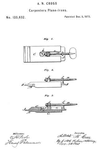
Figure 1 is a plan view, Fig. 2 a side view, and Fig. 3 a longitudinal section, of my invention.
A represents the plane iron or blade, B the cap, and C the case. The case C is in the center, on the front, provided with two slots, a and b, the slot a, extending from the upper edge downward for a suitable distance, and at the lower end of said slot is formed a projection, d, on the outside of the case. Below this projection d is the slot b, running on the same line with the former slot. The blade A is also slotted, as shown in Fig. 3, and is, with the cap B, placed in the case. A screw, e, is then passed through the slot b of the case and through the slot in the blade, and screwed into the cap B, thus securing the blade and cap firmly together. By means of the slot in the blade the cap may be set at any desired distance from the edge of the blade to do good work. On the front side of the blade A, at or near the upper end, is a short post or projection, f the outer end of which has a hole with female-screw threads. Through this is passed a thumb~screw, D, the lower end of which goes loosely through the projection d on the case, and has a nut on its end to prevent its being withdrawn. By means of this thumb-screw D the blade is raised or lowered at will for thin or thick shavings, and, the cap being fastened to the blade, the two are of course adjusted at the same time.
The case C is to be wedged in the stock so as to be firm in the same, the whole forming a very convenient and useful improvement in planes.
Having thus fully described my invention, what I claim as new, and desire to secure by Letters Patent, is —
The within-described plane-iron, consisting of the slotted blade A, cap B, and slotted case C, the blade and cap being adjusted together by the set-screw e placed within the case and operated by the thumb-screw D, in the manner and for the purposes herein set forth.
In testimony that I clairn the foregoing I have hereunto set my hand.
ALBERT N. CROSS.
Witnesses:
E. S. MINER,
B. F. BUCK, JR.