No. 141,828 – Improvement In Crozing And Chamfering Planes (Allen M. Strattan) (1873)

[paiddownloads id=”214″]141828


UNITED STATES PATENT OFFICE.

_________________

ALLEN M. STRATTAN, OF LADOGA, INDIANA.

IMPROVEMENT IN CROZING AND CHAMFERING PLANES.

_________________

Specification forming part of Letters Patent No. 141,828, dated August 12, 1873; application filed March 22, 1873.

_________________

To all whom it may concern:

Be it known that I, ALLEN M. STRATTAN, of Ladoga, in the county of Montgomery, Indiana, have invented an Improvement in Crozing and Chamfering Planes, of which the following is a specification:

This is an improved tool for coopers’ use, and combines the functions of a croze and a charnfering-plane.

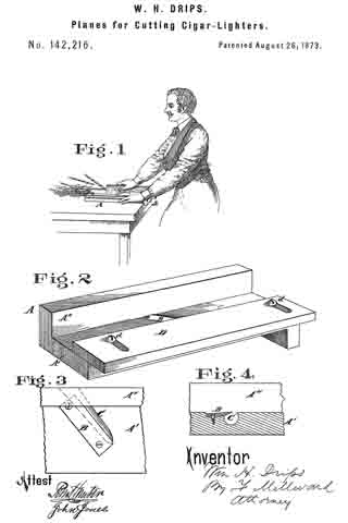
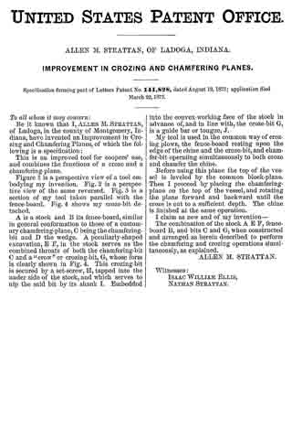
Figure 1 is a perspective view of a tool embodying my invention. Fig. 2 is a perspective view of the same reversed. Fig. 3 is a section of my tool taken parallel with the fence-board. Fig. 4 shows my croze-bit detached.

A is a stock and B its fence-board, similar in general conformation to those of a customary chamfering-plane, C being the chamfering-bit and D the wedge. A peculiarly-shaped excavation, E F, in the stock serves as the combined throats of both the chamfering-bit C and a “crow” or crozing-bit, G, whose form is clearly shown in Fig. 4. This crozing-bit is secured by a set-screw, H, tapped into the under side of the stock, and which serves to nip the said bit by its shank I. Embedded into the convex-working face of the stock in advance of, and in line with, the croze-bit G, is a guide bar or tongue, J.

My tool is used in the common way of crozing plows,the fence-board resting upon the edge of the chine and the croze-bit, and chamfer-bit operating simultaneously to both croze and chamfer the chine.

Before using this plane the top of the vessel is leveled by the common block-plane. Then I proceed by placing the chamfering-plane on the top of the vessel, and rotating the plane forward and backward until the croze is cut to a sufficient depth. The chine is finished at the same operation.

I claim as new and of my invention —

The combination of the stock A E F, fence-board B, and bits C and G, when constructed and arranged as herein described to perform the chamfering and crozing operations simultaneously, as explained.

ALLEN M. STRATTAN.

Witnesses:
ISAAC WILLIAM ELLIS,
NATHAN STRATTAN.

No. 142,216 – Improvement In Planes For Cutting Cigar-Lighters (William H. Drips) (1873)

[paiddownloads id=”215″]142216


UNITED STATES PATENT OFFICE.

_________________

WILLIAM H. DRIPS, OF CINCINNATI, OHIO.

IMPROVEMENT IN PLANES FOR CUTTING CIGAR-LIGHTERS.

_________________

Specification forming part of Letters Patent No. 142,216, dated December 18, 1873; application filed June 24,1873.

_________________

To all whom it may concern:

Be it known that I, WILLIAM H. DRIPS, of Cincinnati, Hamilton county, State of Ohio, have invented a certain new and useful Plane for Cutting Cigar-Lighters, of which the following is a specification:

My invention consists of a small frame, to be placed temporarily upon a table or on the counter of a saloon, cigar-shop, hotel, or other similar place where cigars are sold, the frame containing a fixed plane blade and gage, by means of which the attendant can, with but little labor, make a sufficient number of curled shavings, adapted for cigar-lighters, to form a sufficient stock for the day.

Figure 1 is a general view of my improved tool, showing the method of using my invention. Fig. 2 is a perspective vievv of the tool. Fig. 3 is a plan of the cutter-blade. Fig. 4 is a vertical section of a portion of the frame and cutter-blade.

A is a frame, formed of two strips, A’ A”, of wood, attached at right angles to each other, as shown. The horizontal strip, which rests upon the table or counter, has at one end a lip or flange, a, to engage the edge of the table and prevent it from slipping, said lip being preferably formed in one piece with the strip A’. A cutter-blade, B, of steel, is let obliquely into the plate A’, and secured permanently thereto at each end by screws. Below it is a circular recess, C, which receives the coiled shavings, and allows it to pass out upon the counter. The cutter B is not only let in obliquely in the direction of its length, but is also obliquely located in the direction of its width, so as to cause the shavings to curl anglevvise by its obliquity lengthwise, and cause the knife to present a cutting-edge by its obliquity crosswise. A gage or shield, D, is attached to strip A’ by screws d, the gage being slotted, as shown, to permit adjustment to suit different thicknesses of stud to be cut. This shield prevents the operator’s fingers from touching the knife in the act of pushing the stuff along, in the manner shown, to cut the lighters. The instrument may, however, be made and used without the adjustable gage.

I claim —

As a new article of manufacture, the tool for cutting cigar-lighters, substantially as described.

In testimony of which I hereunto set my hand.

WILLIAM H. DRIPS.

Witnesses:
FRANK MILLWARD,
J. L. WARTMANN.

No. 143,072 – Improvement In Bench-Planes (Cyrus H. Hardy) (1873)

[paiddownloads id=”216″]143072


UNITED STATES PATENT OFFICE.

_________________

CYRUS H. HARDY, OF BOSTON, MASS., ASSIGNOR TO JOHN SULLY, TRUSTEE.

IMPROVEMENT IN BENCH-PLANES.

_________________

Specification forming part of Letters Patent No. 143,072, dated September 23, 1873; application filed May 28, 1873.

_________________

To all whom it may concern:

Be it known that I, CYRUS H. HARDY, of Boston, in the county of Suffolk and State of Massachusetts, have invented certain Improvements in Bench-Planes, of which the following is a specification:

Figure 1 of the accompanying drawing is a central vertical longitudinal section. Fig. 2 is a top view of the shield, and Fig. 3 is a transverse vertical section through a portion of the shield and wedge of my improved plane.

The present invention relates to certain new and useful improvements, applicable, mainly, to metallic bench-planes, and having for their principal objects the providing of a rest and shield for the hand of the operator, to serve as a handle, and to prevent the friction of the hand against the sides or frame of the plane, as well as to allow the blade to be readily inserted in or withdrawn from the plane. My invention consists, mainly, in a plane arranged as will be hereinafter more fully described, with a curved shield or guard formed with forward wedge-like projections, or beveled prongs, inserted between an adjustable wedge or block and the top of the blade, so as to securely hold or be readily withdrawn from the latter and form a protection and rest for the hand.

In the drawings, a represents the bottom of a plane, formed of metal or any other suitable material. Projecting upward on each side of the bottom a are curved sides b, connected near the center at the top by a cross-bar, c. The bottom a is formed with a transverse mouth or slot, d, that receives the front “top-beveled” edge of a blade, e, the bottom of which rests on a transverse vertical standard, f, connecting the sides b, and extending up from the bottom a at a sufficient distance from the rear end of the frame to give a proper angle to the blade e. Extending upward, in front of the mouth d, and across the plane, is a finger-rest, l. Inserted between the cross-bar c and the blade e is a block, g, the forward portion g’ of which is beveled on the top to form a wedge, and whose edges g” are beveled inwardly to receive the forward-projecting beveled ends or prongs Ih’ of a curved shield or guard, h. The projecting ends or prongs h’ are beveled on the inside, and extend forward in a longitudinal tapering shape on the top, with a flat bottom, extending in a semicircular form at the back, where the shield or guard It extends upward, curving horizontally a short distance on the sides, and vertically in a segmental elliptical shape, as shown, or in any other form that may be desired, to form a rest for and a protection to the hand.

The wedge and tapering shape of the prongs h’ allow of their ready insertion between or withdrawal from the wedge-block g and the blade e, so as to securely hold the latter, or to permit of its being easily withdrawn or adjusted to the desired position, the blade e being loosened from its position by striking against a block or lug, m, at the rear of the plane.

Having thus fully described my improvements, what I claim as my invention, and desire to have secured to me by Letters Patent, is —

1. In a bench-plane, a curved shield or guard, lt, having beveled projections or prongs h’, arranged and operating substantially as specified.

2. In a bench-plane, the combination of a curved shield or guard, h, wedge-block g, and blade e, all arranged and operating substantially as described.

In testimony whereof I have signed my name to this specification in the presence of two subscribing witnesses.

CYRUS H. HARDY.

Witnesses:
CARROLL D. WRIGHT,
SAML. M. BARTON.

No. 143,101 – Improvement In Rabbet-Planes (Francis Smith) (1873)

[paiddownloads id=”217″]143101


UNITED STATES PATENT OFFICE.

_________________

FRANCIS SMITH, OF BOSTON, ASSIGNOR TO JOHN SULLY,
TRUSTEE, OF DEDHAM, MASSACHUSETTS.

IMPROVEMENT IN RABBET-PLANES.

_________________

Specification forming part of Letters Patent No. 143,101, dated September 23, 1873; application filed May 28, 1873.

_________________

To all whom it may concern:

Be it known that I, FRANCIS SMITH, of Boston, in the county of Suffolk and State of Massachusetts, have invented certain Improvements in Rabbet-Planes, of which the following is a specification:

Figure 1 of the accompanying drawing is a horizontal section taken in line C D, and showing a top view of my improved plane. Fig. 2 is a side view of my improved plane; and Fig. 3 is a transverse vertical section taken in line A B, and showing an end view of a portion of the plane.

The present invention relates to certain new and useful improvements in metallic rabbet-planes, and has for its principal objects the production of a durable and economical plane that is easily worked, and true and effective in its operation; that may be used either right or left without varying the blade, as it is necessary to do in wooden rabbet-planes when slightly worn; and in which a blade block or wedge is conveniently and readily adjusted without disturbing the position of the blade. My improvements consist, mainly, in a metallic rabbet-plane arranged, as will be more fully described hereafter, so as to admit of the insertion of a wedge or block and blade in the side of the frame or bar of a plane, and to secure the even, smooth, and close cutting of the rabbet.

In the drawing, a represents a metallic plate forming the bottom of a plane, divided by a transverse mouth, b, into two portions, which are connected by a curved bar or “goose-neck,” c, on the rear portion of which, projecting horizontally from one side, are formed flanges d and e, one above and inclined toward the other at the front, thus leaving a wedge-like space between them, in which is inserted a blade, f, the upper portion of which is narrower than the wide bottom portion f’, being cut away for some distance on one side of the upper part, so as to admit of its side entrance. The blade f is formed with a top or reversed bevel edge, k, and finds a seat on the top of the lower flange e, which is inclined at the proper angle to receive the blade, which is held by a wedge or block, g, that is inserted sidewise between it and the upper flange d. The plane is provided at the rear with a suitable handle, h, connected with its bottom a.

Reference being had to the drawing, it will readily be seen that, by the arrangement above described, the blade f and block g are adjusted between the flanges d e from the side of the plane much more conveniently and readily than when, as usual, they are inserted in the top of the plane and driven down; for in the latter case, after the blade is properly set, it is very often liable to be displaced by the driving in of the wedge, and considerable trouble caused and time wasted in readjusting it.

In wooden rabbet-planes, the bottom edge of the frame running against the angle of the rabbet soon becomes worn and uneven, and prevents the true and smooth cutting of the rabbet; but by my improvement the edge, being of iron or other suitable metal, is not liable to be worn so as to interfere with the effective operation of the plane. Moreover, in a wooden rabbet-plane, a spur is necessarily made on its side, in front of the blade, so as to cut out the corner of the rabbet and clear the way for the passage of the blade, so as to cut a clean shaving; but by the formation of the top or reversed bevel edge k in a rabbet-plane, the side edge of the bevel answers the above purpose equally as well if not better than the spur, the use of which is, by my improvement, therefore obviated.

Having thus fully described my improvements, what I claim as my invention, and desire to have secured to me by Letters Patent, is —

The combination of the bar or goose-neck c, formed with flanges d e, and block or wedge g, blade f, and plate a, all arranged substantially as herein set forth.

In testimony whereof I have signed my name to this specification in the presence of two subscribing witnesses.

FRANCIS SMITH.

Witnesses:
CARROLL D. WRIGHT,
SAML. M. BARTON.

No. 143,737 – Improvement In Splint-Planes (Henry L. Weagant) (1873)

[paiddownloads id=”218″]143737


UNITED STATES PATENT OFFICE.

_________________

HENRY L. WEAGANT, OF MORRISBURG, CANADA, ASSIGNOR OF TWO-THIRDS OF HIS RIGHT TO STEPHEN B. FELL AND ROBERT LYLE, OF SAME PLACE.

IMPROVEMENT IN SPLINT-PLANES.

_________________

Specification forming part of Letters Patent No. 143,737, dated October 14, 1873; application filed August 29, 1873.

_________________

To all whom it may concern:

Be it known that I, HENRY LUDWICK WEAGANT, of Morrisburg, in the county of Dundas and Province of Ontario, Canada, have invented new and useful Improvements in Splint-Planes; and I do hereby declare that the following is a full, clear, and exact description of the same.

By my invention a plane or slat-cutter is provided which will produce at each cut a slat, perfectly formed, beveled, properly straightened out, and then receiving the proper bend to facilitate its being woven, reference being had to the annexed drawings, where similar letters of reference indicate like parts, and where —

Figure 1 represents a side view, Fig. 2 a bottom view, and Fig. 3 an end view, of my slat-cutter. Fig. 4. represents a section of my slat-cutter on line A A.

A is the body of the plane or slat-cutter, in which is formed, as shown in Figs. 1, 2, and 4, a recess, A’. In this recess is placed the plane-iron B for cutting the slats, slotted in the ordinary manner, and further secured by a cap or stiffening piece, C. D D’ are the beveling-knives, slotted and secured, one to the side and the other to the bottom of the plane, and arranged so as to cut the beveled edges of the slats. E is a groove formed in the side of the plane, through which the slat just cut passes. F is what is termed the “governor,” placed in the throat E’ of the groove E, and secured preferably by means of a plate or washer and screw, its purpose being to straighten the slats as they pass irom the plane-iron B, the spring G materially assisting in doing this. H is a recess formed in the throat, and serving to give the slat when straightened the proper bend to enable it to be woven. I I are guides to keep the plane in its proper course, and K K’ handles for working the plane or cutter, L being another handle, which may be hinged to the stock, if required.

The operation of my invention is so simple as hardly to require any explanation, it being worked in the same way as an ordinary plane, and being applied to the edge of a board, the thickness of which is the required width of the slat.

The slat, being divided from the board by the iron B, has at the same time its edges beveled by the cutters or knives D D’. It then passes up over the governor F, and between it and the spring G, being thereby straightened, and, the end being caught in the recess H, is thereby slightly bent again, as required.

What I claim is as follows:

The combination of the plane-iron B and beveling-knives D D’ with the governor F, spring G, and recess H, as and for the purposes set forth.

HENRY L. WEAGANT.

Witnesses:
ROBERT LYLE,
ROBERT S. WEAGANT.

No. 144,381 – Improvement In Bench-Planes (William H. Brown And David F. Williams) (1873)

[paiddownloads id=”219″]144381


UNITED STATES PATENT OFFICE.

_________________

WILLIAM H. BROWN, OF WORCESTER, MASSACHUSETTS, AND DAVID F.
WILLIAMS, OF WOONSOCKET, ASSIGNORS TO BAILEY TOOL COMPANY, OF WOONSOCKET, RHODE ISLAND.

IMPROVEMENT IN BENCH-PLANES.

_________________

Specification forming part of Letters Patent No. 144,381, dated November 11, 1873; application filed April 12, 1873.

_________________

To all whom it may concern:

Be it known that we, WM. H. BROWN, of Worcester, in the county of Worcester and State of Massachusetts, and DAVID F. WILLIAMS, of Woonsocket, in the county of Providence and in the State of Rhode Island, have invented a new and useful Improvement in Bench-Planes; and we do hereby declare that the following is a full, clear, and exact description thereof, reference being had to the annexed drawings making a part of this specification, in which —

Figure 1 represents our improved bench-plane in perspective, and Fig. 2 a vertical longitudinal section of the same.

Our invention consists in certain hereinafter-described means provided for the purpose of facilitating the adjustment of the cap, and for regulating the pressure upon the cutting-tool.

The general construction of our bench-plane is like that described in Letters Patent No. 105,767, granted Joseph R. Bailey, July 26, 1870, an eccentric or curved bar, A, being used in conjunction with a presser-plate, B, to secure the plane-iron D and intervening cap C in the stock E. The presser-plate in this case is elongated and provided with a head, D, and a set-screw, d, the former of which acts in conjunction with other parts presently to be described, while, by means of the lathe, the pressure of said plate against the cam-rod may be adjusted so as to permit of the use of a thick or thin cap or cutting-iron, as desired. It also has lugs e, which project into grooves f cut in each side of the flanges of the stock, at right angles to the cutting-tool, whereby the slipping or sliding of the plate forward or backward is prevented, while at the same time it is allowed to rise and fall under the action of the set-screw d. The accurate adjustment of the cap with reference to the cutting edge of the chisel and the throat of the stock is obtained by means of a set-screw, F, which is carried in a screw-threaded eye in ear c of the cap, and bears with its point against the head b of the presser-plate. The foot of set-screw F being pointed, as shown, a V-shaped groove is formed in the end of head b, to receive such point, and allow the presser-plate to rise and fall and keep it in its exact position.

In the adjustment of the parts, the cap should be properly arranged by adjusting the set-screw F before the eccentric bar is turned down to force the presser-plate against the cap.

We claim as our invention —

1. In a bench-plane of the character described, an adjusting-screw, F, working in an ear, c, formed on or attached to the cap, combined with the presser-plate B, provided with the grooved head b, substantially as and for the purpose set forth.

2. The eccentric A, presser-plate B with lugs e e, grooves f f, and set-screw d, in combination with the cap or plane-iron.

3. The presser-plate B, with lugs e e, in combination with cap C c, set-screw F, and grooves f f substantially as described.

In testimony that we claim the above-described improvement we have hereunto signed our names this 5th day of April, 1873.

WM. H. BROWN.
DAVID F. WILLIAMS.

Witnesses:
F. T. BLACKMER,
W. W. RICE.