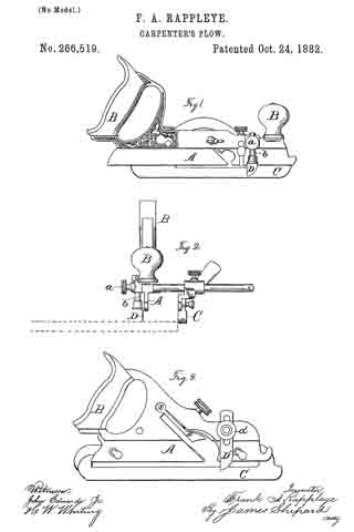
No. 280,175 – Match-Plane (Philip Hickey) (1883)

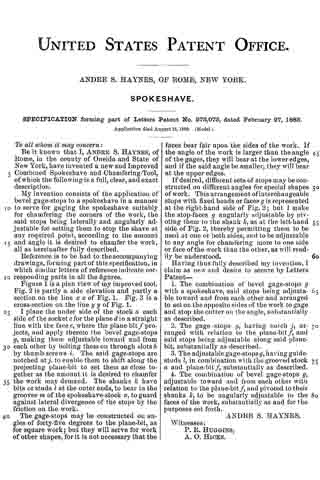
UNITED STATES PATENT OFFICE.
_________________
PHILIP HICKEY, OF BOSTON, MASSACHUSETTS.
MATCH-PLANE.
_________________
SPECIFICATION forming part of Letters Patent No. 280,175, dated June 26, 1883.
Application filed April 28, 1883. (No model.)
_________________
To all whom it may concern:
Be it known that I, PHILIP HICKEY, of Boston, in the county of Suffolk and State of Massachusetts, have invented certain new and useful Improvements in Match-Planes, of which the following is a full, clear, and exact description.
The main object of this invention is to adapt a match-plane for it to be used for the making both of a tongue and a groove fitting each other without changing the plane or bit iron, and also another object is to adapt a match-plane, by simply substituting one plane or bit iron for another, for the making of tongues and grooves of varying widths, but as to the grooves and tongues made by either of the irons so substituted, secure the perfect fitting or jointing.
In this improved match-plane the bit or plane iron is of a forked shape at its cutting-edge — that is, it has two separate cutting edges or blades, between which is an opening of a width which determines the width of tongue cut by the plane and the cutting-blade. The outer of the two, relative to the working-face of the gage upon the bottom or sole of the plane, is of a width equal to the width of said opening between the cutting-blades, or, in other words, of the width of the tongue out by the plane, and said gage is attached to the bottom or sole of the plane-stock, so as to be adjusted transversely thereon, and set either for the cutting of a tongue with both of the blades, or of a groove with said outer blade only of the two blades. The other blade being covered by said gage is thus put out of operative position, and all in a manner to secure a perfect fitting of said tongues and grooves so cut when joined together, and otherwise, substantially as hereinafter described.
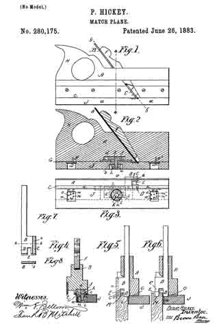
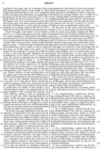
In the accompanying plate of drawings the present improved plane is illustrated, Figure 1 being a side view; Fig. 2, a longitudinal vertical section through the plane and gage; Fig. 3, a face view of the bottom or sole with gage adjusted and set for the cutting of a tongue. Fig. 4 is a cross vertical section on line 4 4, Fig. 1; Fig. 5, a cross vertical section on line 5 5, Fig. 1, which is along the upper face of the plane or bit iron; Fig. 6, a similar view to Fig. 5, but with the gage adjusted and set for the cutting of a groove instead of a tongue, as in Fig. 5, and in the preceding figures. Fig. 7 is a face view of the plane or bit iron detached, and Fig. 8 a cross-section on line 8 8, Fig. 7.
In the drawings, A represents the stock of a match-plane; B, the plane or bit iron, made of a fork shape, or, in other words, with two cutting blades or edges, C D, leaving an opening, E, between them; F, the wedge for fastening the plane-iron B in position; G, the bottom or sole of the stock A; H, the toat or handle, and J the gage running along the length of the sole or bottom G to the stock, and otherwise, except as hereinafter particularly described, the same as ordinary in match-planes for cutting a tongue along the edge of a board, the width of which is determined by the width of the opening E between the two cutting-blades C D.
The cutting-blade C, which is the outer one of the two blades C D relating to the working-face a of the gage J, in its position for the cutting either of a tongue or groove, as the case may be, (see Figs. 5 and 6,) is of a width equal to the width of the opening E between the two cutting-blades, and in the use of this plane, as will hereinafter appear, it of itself and alone cuts the groove.
The gage J is attachable to and detachable from the sole or bottom G of the plane-stock A, and is secured in place by a headed screw-bolt, K, and screw-nut L.
The bolt K passes loosely through the thickness of the gage J and a slot, b, of a plate, c, attached to and covering a recess, d, in the bottom. or sole G of the plane, and the bolt-head f is in said recess, and the recess d, together with said slot b, are in a line at right angles to the working-face a of the gage J, and of a length to allow thc gage to be laterally adjusted upon the sole G of the plane for the purposes of this invention.
g g2 are two projecting pins, one near each end of the sole of the plane, and in a parallel line with the working-face a of the gage.
m m2 and n n2 are four holes to receive the pins g g2. These holes are situated two at each end of the face of the gage which is next to the sole of the plane, and the two at each end are in a line at right angles to the working-face of the gage, and at a distance from each other axially equal to the width of the tongue M which the plane-iron B is adapted to cut, and they are otherwise so arranged that the gage can be set upon the pins g g2 of the plane either by the two holes m and m2 or by the holes n and n2, in each instance one at each end of the gage, and when so set in either case have the working-face a of the gage in proper position for working against the face of the board to be tongued or grooved along its edge.
To set the gage J by either of its holes m and m2 or n n2 upon the pins g g2 of the plane, it is only necessary to first release the fastening nut and bolt K L, and then, having placed it by its holes desired upon the pins, to tighten up said bolt and nut, thus firmly fixing the gage in place. With the gage J adjusted and set as described, by its holes m and m upon the pins g g2 of the plane, the plane is adjusted for the cutting of a tongue, M, as shown in Fig. 5, and with the gage adjusted and set as described, by its holes n and n2 upon said pins, the plane is adjusted for the cutting of a groove, N, as shown in Fig. 6. In the first instance said setting of the gage exposes the two blades C D of the plane-iron for cutting the edge of the board, and in the second instance said setting of the gage leaves only one cutting-blade, and that the outer, C, of the two blades relative to the working-face a of the gage, and covers up the other blade, D, or, in other words, places it out of operative position, and as the distance between the holes m m2 and n n2 of each set of holes equals the width of tongue which the plane-iron B can cut, and the width of the outer cutting-blade, C, equals also the width of said tongue, it is obvious that by these two adjustments of the gage, together with a plane-iron having an outer cutting-blade, C, and an opening between it and the other cutting-blade, D, of equal width, the same plane, using only one plane-iron, is capable of adjustment for the cutting either of a tongue or of a groove, which tongue and groove, when cut, will fit each other and secure a perfect match, of course provided boards are used of the proper thickness.
To render the gage adjustable with the substitution of plane-irons for the plane-iron B, particularly shown in the drawings — that is, plane-irons having a different width of opening E between their two cutting-blades C D, and their outer cutting-blade equal to the width of said opening — and thus to render one and the same plane capable of cutting grooves and tongues of different widths, but in each instance, with the use of any iron, secure a tongue and a groove of the same width when the gage is properly adjusted therefor, the gage is provided with a series of holes — such as o o2 and p p2 — arranged and located and otherwise in every respect similar to the holes m m2 n n2, before described, varying only in this respect, (if it may be termed a variation,) that the transverse distance of each of said sets of holes corresponds to the width of groove and tongue which the plane is to and can cut when another plane-iron of different width of opening E between its cutting-blades and a width of outer cutting-blade corresponding thereto is substituted for the plane-iron B, particularly shown in the drawings, and the gage is properly placed with its set of holes o o2 p p2 belonging to the so-substituted plane-iron.
As the pins of the plane and the setting-holes m m2 n n2 of the gage are fixed points, in order to insure the proper locating of different plane-irons in the plane relative thereto, a groove, s, is made in the back of the outer cutting-blade, C, of each plane-iron, (see Figs. 7 and 8,) to fit over the edge t of the plane opposite to that of the gage, and, as the pins g g2 of the plane and the setting-holes m, m2, n, and n2 of the gage are located in the drawings, the groove is along the center line of the width of said cutting-blade; but it is plain that, were either the setting-holes or the pins located differently relative to the position of the plane-iron in the plane, the position of said groove would be necessarily changed. The pins g g2 may be on the gage and the holes m m2 n n2 in the plane, and, as is obvious, these means absolutely insure the adjustment herein described of the gage to the plane-iron used. It is plain, however, that other means might be substituted for said pins and holes, and yet insure absolutely said adjustments of the gage.
The screw-nut of the fastening device for the gage is preferably countersunk in a recess, u, of the gage, and in lieu of the fastening device for the gage particularly described and shown others may be substituted.
Having thus described my invention, what I claim, and desire to secure by Letters Patent, is —
1. In a match-plane, a plane-iron, B, having cutting-blades C D, with an opening, E, between them, and the outer blade of the width of the tongue to be cut and of said opening, in combination with a gage, J, adapted for arbitrary and rigid adjustment, substantially as and for the purpose described.
2. In a match-plane, a plane-iron, B, having cutting-blades C D, with an opening, E, between them, and the outer blade, C, of the width of the tongue to be cut and of said opening, in combination with a gage, J, adapted by pins g g2 and holes m m2 n n2, together with a suitable fastening device, to be adjusted, substantially as described, for the purposes specified.
3. In a match-plane, a plane-iron, B, having cutting-blades C D, with an opening, E, between them, and an outer blade, C, of the width of the tongue to be cut and of said opening, and adapted to interlock; with the flange or rib t of the plane, in combination with an adjustable gage, substantially as and for the purpose described.
4. In a match-plane, a plane-iron, B, having cutting-blades C D, with an opening, E, between them, and the outer blade, C, of the width of the tongue to be cut and of said opening, in combination with a gage adapted by sets of pins g g2 and holes m, m2, n, and n2, together with a suitable fastening device, to be adjusted for different plane-irons of the above-said construction, substantially as and for the purpose described.
In testimony whereof I have hereunto set my hand in the presence of two subscribing witnesses.
PHILIP HICKEY.
Witnesses:
EDWIN W. BROWN,
WM. S. BELLOWS.