No. 211,515 – Improvement In Bench-Tools (James H. Lewis) (1879)
UNITED STATES PATENT OFFICE.
_________________
JAMES H. LEWIS, OF DETROIT, MICHIGAN, ASSIGNOR OF ONE-HALF HIS RIGHT TO GEORGE H. STELLWAGEN, OF SAME PLACE.
IMPROVEMENT IN BENCH-TOOLS.
_________________
Specification forming part of Letters Patent No. 211,515, dated January 21, 1879; application filed September 18, 1878.
_________________
To all whom it may concern:
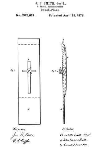
Be it known that I, JAMES H. LEWIS, of Detroit, in the county of Wayne and State of Michigan, have invented an Improvement in Bench-Tools, of which the following is a specification:
The nature of my invention relates to certain new and useful improvements in hand or bench tools of the spokeshave class for working curved moldings, having for its object to so construct the same as to enable the operator to work with the grain of the timber when it reverses in direction, thus avoiding the expense of a second tool of the same configuration.
The invention consists in providing the segment stock or head with two throats and cutters, inclined toward each other, as is more fully hereinafter set forth.
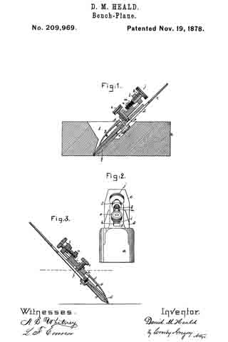
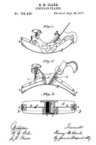
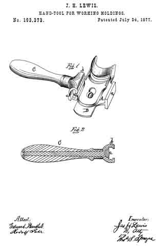
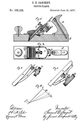
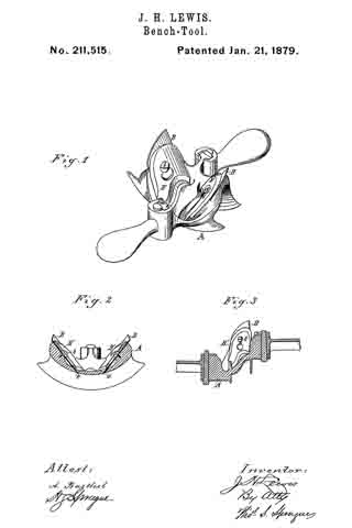
In the drawings, Figure 1 is a perspective view of my device. Fig. 2 is a cross-section of the same; and Fig. 3 is a vertical longitudinal section, showing the relative position of the centers.
In the accompanying drawings, which form a part of this specification, A represents a metal stock or head, being a segment whose face has the cross-section of the molding that is to be produced. a are throats, inclined toward each other, as shown, and in which are secured the cutter-bits B by means of clamp-plates B’ and screws b, or in any other convenient manner. These bits have a contour at the cutting-edge adapted to produce a molding of the desired cross-section, but are designed to out in opposite directions, so that in working a curved molding either bit may be used to cut with the grain when it reverses its direction, as it necessarily does, thus avoiding the necessity of having a pair of such tools for working each pattern of molding, the one having a reverse cut from that of the other.
The handles are made detachable, as shown; but it is evident that the stock may be provided with permanent or stationary handles, if desired.
What I claim as my invention is —
The bench-tool described, consisting of the segmental head A, having the throats a a and the cutters B, secured in opposite directions in said head by the adjustable plates B’ and screw b, substantially as and for the purpose set forth.
JAMES H. LEWIS.
Witnesses:
H. S. SPRAGUE,
A. BARTHEL.