
No. 192,402 – Improvement In Bench-Planes (Clinton L. Adancourt) (1877)
UNITED STATES PATENT OFFICE.
_________________
CLINTON L. ADANCOURT, OF LANSINGBURG, NEW YORK.
IMPROVEMENT IN BENCH-PLANES.
_________________
Specification forming part of Letters Patent No. 192,402, dated June 26, 1877; application filed December 15, 1876.
_________________
To all whom it may concern:
Be it known that I, CLINTON L. ADANCOURT, of the town of Lansingburg, Rensselaer county and State of New York, have invented an Improvement in Bench-Planes, of which the following is a specification:
The nature of my invention consists in forming a wood-plane in adjustable sections, which may be attached to its ends, so as to increase the length of its bearing-surface when required, to vary the uses to be performed by it, and thus make one plane answer a double use by lengthening the same.
It also consists in the manner of attaching and operating the cutting bit or knife to the plane, so that the same may be used to cnt a shaving of greater or less thickness.
My invention consists of these separate features as arranged and constructed, as well as the same combined.
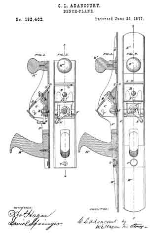
In the accompanying drawings, Figure 1 shows a vertical sectional view of a central section of a plane without the extension sections. Fig. 2 illustrates the same section in a top view looking down upon the plane, with the handle removed. Fig. 3 represents a vertical sectional view with the extension-sections added; and Fig. 4, a top view of the plane with extension-sections added.
Like letters designate like parts in all the figures.
The detachable handles of the plane are designated H’ H”, the cutting bit or knife B, and a hinged bank C, upon which the latter rests, and to which it is attached. The trunnions upon which the bank C is hinged to the side walls of the plane are shown at T; the cutting-edge of the bit at O; the shaving-discharge opening of the plane at S.
The cutting bit or knife is illustrated as attached to the hinged bank by means of a slotted opening in the knife, and a set-screw, as seen at I. Upon the under side of the hinged bank, and against it, so as to more it and the attached bit or knife upon the hinged apex of the former, there is shown an eccentric, e, with a handle, E. This latter is attached to the base of the plane by a screw, K. The extension-sections E’ E” are attached to the central section F by means of lapping and tenoned joints, and are secured and held in place by the set-screws S” S”, passing through the lapping and tenoned points of union, and attaching the handles of the plane.
The manner of operating the device thus formed is as follows: The cutting knife or bit B, as attached to the bank C hinged at T, is shown as in contact, upon its inner edge, with the eccentric e and its handle E, and when this handle is moved in the direction of the arrows, shown upon the eccentric at a”, the motion communicated to the bank in contact is such as to raise or depress the lower end of the bank and knife by moving the same in the direction of the arrows seen at a’ and a”. The shaving-cut will be in proportion to the dip of the bit, and this is arranged by the adjustable eccentric and handle, as it is moved around the fixed pin, the eccentric raising or depressing the cutting end of the knife.
The knife or bit, which is sharpened at both ends, may, if desired, have one end rounded, like the edge of a jack-plane knife, for coarse work, and the other with a straight cutting-edge, like a smoothing-plane, so that the knife may be reversed and used tor either kind of work, and, by the addition of the extension-section, what would serve for a jack-plane body may be changed into that of a jointer, and thus one tool maybe made to answer the purpose of several.
The body of the planes and the extension-sections may be made of either wood, iron, or other suitable material.
Having thus described my invention, what I claim, and desire to secure by Letters Patent, is —
1. In combination, the center knife or bit section F of a plane, and the extension-section E’ E”, to increase the length and base bearing-lines of the plane, as shown and described.
2. In a bench-plane, the hinged bank C, reversible cutting bit or knife B, actuating-eccentric e, and handle E, arranged to operate as described and shown.
3. In a bench-plane, the extension-sections E’ and E”, the center or bit section F, the hinged bank C, cutting bit or knife B, the adjusting-eccentric e, and handle E, arranged to operate as herein described and shown.
Signed at Troy, New York, this 12th day of December, 1876.
C. L. ADANCOURT.
Witnesses:
CHAS. M. DAVIS,
THOS. F. MURNANK.