No. 250,007 – Bench-Plane (George F. Sawyer) (1881)

UNITED STATES PATENT OFFICE.
_________________
GEORGE F. SAWYER, OF LIBERTY, TEXAS.
BENCH-PLANE.
_________________
SPECIFICATION forming part of Letters Patent No. 250,007, dated November 22, 1881.
Application filed July 5, 1881. (No model.)
_________________
To all whom it may concern:
Be it known that I, GEORGE F. SAWYER, of Liberty, in the county of Liberty and State of Texas, have invented certain useful Improvements in Plane Attachments, of which the following is a specification.
The object of my invention is to prevent dulling the cutting-edge of a plane-iron by the backward movements of the plane.
The invention consists in a stirrup pivoted to the sides of the plane in such a manner that the transverse piece of the stirrup passes through a transverse groove in the under surface of the plane, this groove increasing in height toward the rear of the plane, so that when the plane is drawn backward it will be slightly raised by this stirrup, so that the cutting-edge of the plane-iron cannot slide on the board being planed.
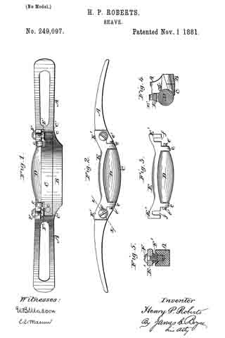
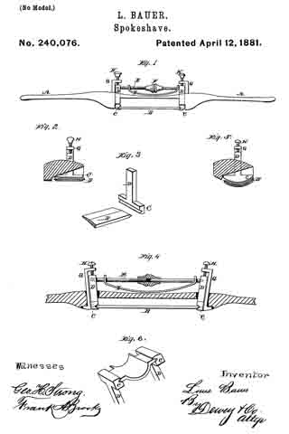
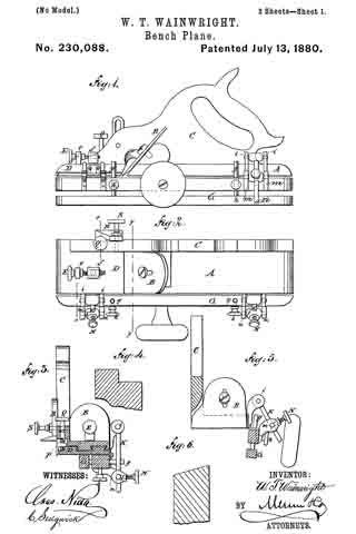
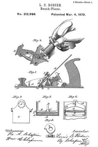
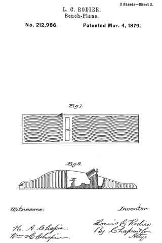
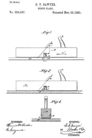
In the accompanying drawings, Figure 1 is a longitudinal elevation of a plane provided with my improved attachment, the same being shown in the position it has when the plane is being moved backward. Fig. 2 is a like elevation, showing the plane moving forward. Fig. 3 is a cross-sectional elevation of the same on the line x x, Fig. 1.
Similar letters of reference indicate corresponding parts.
A stirrup, A, of the same width as the plane B, has the outer surface of its transverse piece or bar C rounded or cylinder-shaped. This stirrup A is pivoted to the plane B in such a manner that the shanks of the stirrup extend into the recesses D in the lower parts of the sides of the plane, these recesses being united by a transverse groove, E, in the under or bearing surface of the plane, the transverse bar C passing through this groove. The groove increases in depth or height from the front to the rear on a curved line.
The operation is as follows: If the plane is moved in the direction of the arrow x’, as shown in Fig. 1, the stirrup A swings to the front edge of the recesses D, and is held in that position on account of the movement of the plane; but, the stirrup-shanks being longer than the distance from the pivot to the under side of the plane, the plane must be raised a short distance and the cutting-edge of the plane-iron G cannot slide on the board F, and consequently will not become dull or blunted; but when the plane is moved forward in the direction of the arrow y’, as shown in Fig. 2, the stirrup swings back and the plane is lowered, and the cutting-edge of the plane-iron G cuts into the board F.
This device is simple and can be attached to old as well as new planes.
I am aware that it is not broadly new to provide planes with rollers adapted to elevate the cutter above the board when the plane is being drawn backward.
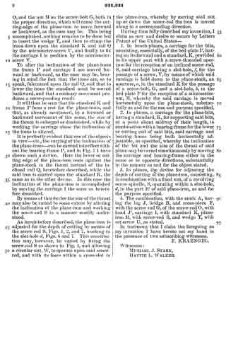
Having thus described my invention, I claim as new and desire to secure by Letters Patent —
1. The combination, with a plane having lateral recesses and a transverse groove in its under surface, of a suitable stirrup having its shanks pivoted in said recesses and adapted to slide into said groove, substantially as shown and described.
2. The combination, with the plane B, provided with recesses D in the sides and a transverse groove, E, in the under surface, of the stirrup A, pivoted to the plane, substantially as herein shown and described, and for the purpose set forth.
GEORGE FREDERIC SAWYER.
Witnesses:
W. B. TAYLOR,
D. C. PALMER.