No. 231,990 – Bench-Plane (August P. J. Bossel) (1880)
[paiddownloads id=”311″]231990


UNITED STATES PATENT OFFICE.

_________________

AUGUST P. J. BOSSEL, OF VIRGINIA CITY, NEVADA.

BENCH-PLANE.

_________________

SPECIFICATION forming part of Letters Patent No. 231,990, dated September 7, 1880.
Application filed June 29, 1880. (No model.)

_________________

To all whom it may concern:

Be it known that I. AUGUST P. J. BOSSEL, of Virginia City, in the county of Storey and State of Nevada, have invented a new and useful Improvement in Planes, of which the following is a specification.

My invention is more particularly intended for planes used in rabbeting, but it is applicable to planes of various kinds.

The invention consists, first, in a novel construction, arrangement, and combination, with the plane-bit, of a toothed plate or rack, and a pinion for adjusting the bit, and a wedge for holding it when adjusted; and, further, in a novel arrangement of the handle of the plane and devices connected therewith for adjusting said handle at different positions.

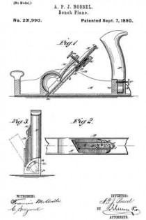
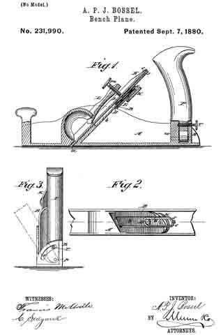
In the accompanying drawings, Figure 1 is a longitudinal vertical section of a plane embodying my irnprovements. Fig. 2 is a top view of a portion of the same with the bit and wedge removed. Fig. 3 is a rear-end view.

Similar letters of reference indicate corresponding parts.

The plane A is preferably made of metal, and the throat a may be of the usual description. At the top of the throat a, is an upwardly-projecting lug or plate, B, in which is journaled a short shaft, the front end of which carries a pinion, D. The rear end of this shaft may have a milled knob attached directly to it, but as here represented it carries a gear-wheel, E, with which engages another gear-wheel, G, carried by one end of a short shaft journaled in said plate B, and having at its other end a milled knob, H.

ln a recess, b, on the front side of the plate B, works a sliding rack, J, with which the pinion D engages. Near the upper end of the rack J, and on the front side thereof, is a projecting pin or stud, s, which engages with a hole in the plane-bit K, near the upper end thereof. By turning the pinion D in one direction or the other the bit K is adjusted up or down in order to regulate its cut.

The wedge L is provided with a thumb-screw, m, which passes through it and bears against the front surface of the bit K. When the bit has been adjusted to the desired position the screw m is tightened so as to hold the bit firnily in place by the combined pressure of said screw and of the lower end or point of the wedge. By the means above described the bit may be readily adjusted with exact nicety without the use of a hannner, as in the ordinary plane.

The handle P, instead of being rigidly attached to the plane, is pivoted at p between a quadrantal plate R, extending upward from the plane near the rear end thereof, and a lug, u’, in front of said plate R.

A thumb-screw, T, passes through an arc-shaped slot, v, in the plate R, and through the handle P above the pivot p, and bears against the lug w, and thus holds the handle firmly in position. When the plane is used in a corner or near a surface where space tor the handle and the hand is limited the handle P may be inclined, as indicated in dotted lines in Fig. 3, and held firmly in position by the screw T.

Having thus described my invention, what I claim as new, and desire to secure by Letters Patent, is —

1. A plane consisting of the body A, provided with the upwardly-extending plate B, having the recess b, the rack J, sliding in said recess, the bit K, having its shank elongated and connected to said rack by the pin or stud s, the pinion D, operating said rack, and the wedge L, provided with the thumb-screw m, substantially as herein described.

2. The handle P, pivoted at p, the are-slotted plate R, and the lug w, in combination with the thumb-screw T, as and for the purpose specified.

AUGUST P. J. BOSSEL.

Witnesses:
D. J. MACINTOSH,
W. COYNE.

No. 231,331 – Bench-Plane (Frederic Kraengel) (1880)

[paiddownloads id=”310″]231331


UNITED STATES PATENT OFFICE.

_________________

FREDERIC KRAENGEL, OF BUFFALO, NEW YORK, ASSIGNOR OF ONE-HALF OF HIS RIGHT TO EMIL JETTER AND ALBERT JETTER, OF SAME PLACE.

BENCH-PLANE.

_________________

SPECIFICATION forming part of Letters Patent No. 231,331, dated August 17, 1880.
Application filed April 30, 1880. (No model.)

_________________

To all whom it may concern:

Be it known that I, FREDERIC KRAENGEL, of Buftalo, in the county of Erie and State of New York, have invented certain new and useful Improvements on a Bench-Plane; and I do hereby declare that the following description of my said invention, taken in connection with the accompanying sheet of drawings, forms a full, clear, and exact specification, which will enable others skilled in the art to which it appertains to make and use the same.

This invention has general reference to planes; and it consists in certain peculiar combination of parts and details of construction whereby the plane iron or irons are rendered adjustable, and the throat of the plane-stock enlarged or diminished, substantially in a manner as hereinafter first fully set forth and described, and then pointed out in the claims.

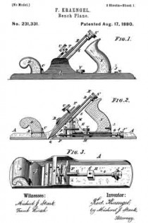
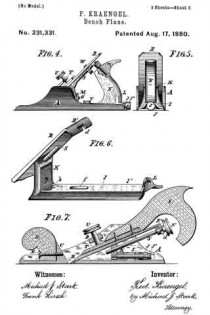
In the drawings already referred to, which serve to illustrate my said invention more fully, Figure 1 is a side elevation of a bench-plane embodying my invention. Fig. 2 is a longitudinal sectional elevation of the same. Fig. 3 is a perspective view of the plane-stock. Fig. 4. is a side elevation of a plane slightly modified. Fig. 5 is an end elevation of the same. Fig. 6 is a perspective view of the carriage, and Fig. 7 a longitudinal sectional elevation of a plane having a single plane-iron and its manner of adjustment slightly modified.

Like parts are designated by corresponding letters of reference in all the figures.

A represents the metallic plane-stock, the sides of which are raised centrally and provided with a bridge, B. In front of this bridge I provide a cross-piece, C, to which is fastened the front handle or knob, D, by means of a screw, E. In the rear of the bridge B, I provide another cross-piece, F, to which is fixed a rearwardly-projecting screw-bolt, G, and in rear of this cross-piece I provide a rise or boss, H, while near the tail of said stock I provide a lug, J.

Within the sides of the stock A, and in rear of the cross-piece F, I place a carriage, I, (shown in detail in Fig. 6,) said carriage consisting of a curved base-plate, I’, having on one end a standard, K, and on the other end a lug, L. In this standard I provide an aperture, a, for the passage of the bolt G, and in the bed-plate J’, close to the standard K, an aperture, b, for the reception of part of a nut, M, engaging said screw G. To the lug L on said carriage is fitted a handle, N.

Within the lug J, on the rear end of the stock A, I swivel a screw-rod, O, extending forwardly through the rise H and cross-piece F into a frame, l’, the forward rail, Q, of which is beveled on its upper surface to correspond somewhat to the inclination ofthe plane-irons R.

The cutting-iron has on its upper end a right-angled bend, R’, provided with a curved notch, d, into which is passed a rod, S, having on its upper end a head, S’, on its opposite end a screw-thread engaging a female thread in near the upper end of the standard K.

These plane-irons are clamped into position by a clamping-plate, T, interposed between the bridge B and said plane-irons, said clamping~plate having a micrometer-screw, U, arranged to press upon said plane-irons.

In the carriage I, I provide a slotted aperture, f, through which is passed a micrometer-screw, V, having its female thread in an aperture, g, in the lug H.

The object of constructing a plane as described is to enable me to vary the inclination of the plane-irons, and also to close or open the throat of the plane-stock by means of said irons, and these results are accomplished in the following manner:

It being desired to close or open the throat of the plane-stock, the irons are first adjusted to the thickness of shaving or cutting required. This is done by turning the head S’ of the screw-rod S in one or the opposite direction. The screw-rod S, having a fixed nut in the standard K and a swiveling connection with the plane-iron in the curved slot-hole d, Fig. 6, works the plane-iron up or down, in accordance with the direction in which it is turned, until the cutting-edge of said iron projects beyond the lower plane surface the desired distance. lf now a wider or narrower throat is wanted I first move the bearing-frame P, Fig. 3, by means of the head J’ on the screw-rod O, and the nut M on the screw-bolt G, both in the proper direction, which will cause the cutting-edge of the plane-iron to move forward or backward, as the case may be. This being accomplished, nothing remains to be done but to insert the wedge T, and then to clamp the irons down upon the standard K and rail Q by the micrometer-screw U, and finally to fix the carriage I in position by the micrometer-screw V.

To alter the inclination of the plane-irons the frame P and carriage I are moved forward or backward, as the case may be, bearing in mind the fact that the irons are, so to speak, fulcrumed upon the rail Q, and that to lower the irons the standard must be moved backward, and that a contrary movement produces a corresponding result.

It will thus be seen that the standard K and frame P form a rest for the plane-irons, and that, as already mentioned, by a forward or backward movement of the same, the size of the throat is enlarged or diminished, while by working the carriage alone the inclination of the irons is altered.

It is perfectly evident that one of the objects in view — viz., the varying of the inclination of the plane-irons — can be carried into effect without the bearing-frame P, and in Fig. 7 I have shown such a device. Here the lower or cutting edge of the plane-iron rests against the plane-stock in the throat instead of the inclined rail Q, heretofore described, while the said iron is carried upon the standard K, the same as in the other device. In this case the inclination of the plane-iron is accomplished by moving the carriage I the same as heretofore described.

By means of this device the size of the throat may also be varied to some extent by altering the inclination of the plane-iron and working the screw-rod S in a manner readily understood.

As hereinbefore described, the plane-iron is adjusted for the depth of cutting by means of the screw-rod S, Figs. 1, 2, and 7, working in the slot-hole d, Figs. 6 and 7. This construction may, however, be varied by fixing the screw-rod S as shown in Fig. 4, and allowing a circular nut, W, to operate upon said screw-rod, and with its faces within a cross-slot in the plane-iron, whereby by moving said nut up or down the screw-rod the iron is moved along in a corresponding direction.

Having thus fully described my invention, I claim as new and desire to secure by Letters Patent of the United States —

1. In bench-planes, a carriage for the bits, consisting, essentially, of the bed~plate I’, having on its forward end a standard, K, provided in its upper part with a screw-threaded aperture for the reception of an inclined screw-rod, S, said carriage having a slot-hole, f, for the passage ofa screw, V, by means of which said carriage is held down to the plane-stock, an aperture, a, in the standard K for the passage of a screw-bolt, G, and a slot-hole, b, in the bed-plate I’ for the reception of a micrometer-nut, M, whereby the said carriage is moved horizontally upon the plane-stock, substantially as and for the use and purpose specified.

2. In planes, a carriage for the plane-bits, having a standard, K, for supporting said bits, at a point about midway of their length, in combination with a bearing-frame for the lower or cutting end of said bits, said carriage and bearing-frame being both horizontally adjustable, as specified, whereby the inclination of the bit and the size of the throat of said plane may be varied simultaneously by moving the carriage and bearing-frame either in the same or in opposite directions, substantially in the manner as and for the object stated.

3. In planes, the device for adjusting the depth of cutting of the plane-iron, consisting, in combination with a fixed nut, of a revolving screw-spindle, S, operating within a slot-hole, d, in the part R’ of said plane-iron, as and for the purpose specified.

4. The combination, with the stock A, having the lug J, bridge B, and cross-piece F, with the screw-rod G, of the screw-rod O, with head J’, carriage I, with standard K, plane-iron R, with screw-rod S, and wedge T, with set-screw U, as stated.

In testimony that I claim the foregoing as my invention I have hereto set my hand in the presence of two subscribing witnesses.

F. KRAENGEL.

Witnesses:
MICHAEL J. STARK,
HATTIE L. WALKER.

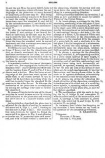
No. 230,088 – Bench-Plane (William T. Wainwright) (1880)

[paiddownloads id=”309″]230088


UNITED STATES PATENT OFFICE.

_________________

WILLIAM T. WAINWRIGHT, OF DRY SAWMILL, PENNSYLVANIA.

BENCH-PLANE.

_________________

SPECIFICATION forming part of Letters Patent No. 230,088, dated July 13, 1880.
Application filed April 28, 1880. (No model.)

_________________

To all whom it may concern:

Be it known that I, WILLIAM T. WAINWRIGHT, of Dry Sawmill, in the county of Elk and State of Pennsylvania, have invented a new and useful Improvement in Planes, of which the following is a specification.

My invention consists in certain novel details of construction and arrangement of parts, whereby the same tool may be used for square-jointing, for beveling, and for rabbeting, as hereinafter particularly described.

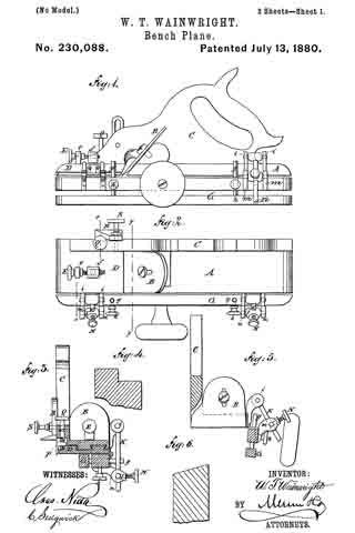
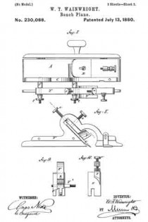
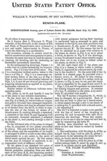
In the accompanying drawings, Figure 1 is a side view of a plane embodying my improvements. Fig. 2 is a top view of the same. Fig. 3 is a transverse vertical section taken in the line x x of Fig. 2. Fig. 5 is a transverse vertical section taken in the line y y of Fig. 2. Figs. 4. and 6 are views hereinafter referred to. Figs. 7, 8, 9, and 10 are views of grooving and tonguing attachments as applied to my plane, hereinafter referred to.

Similar letters of reference indicate corresponding parts.

The plane A, bit B, and handle C may be of the usual or any suitable description.

To the front end of the plane is attached (see Fig. 3) a block, D, which slides on tongue-and-groove dovetail ways arranged longitudinally of the plane, and may be adjusted nearer to or farther from the bit B, in order to regulate the size of the throat, by means of a thumb-screw, E, working through a standard, e, attached to the block D, and engaging with an internally-threaded standard, f attached to the plane A, and passing through a slot in the block.

To the left-hand side of the plane is hinged a bar, G, composed of two pieces connected by pins g. One end of each pin is fast to one of the pieces, and the remainder of its length is arranged to slide in a hole in the other piece transversely to a set-screw, lt, the point of which bears against the pin. By this means the bar may be widened or narrowed, to accommodate work of different widths.

To the plane A are attached two pairs of perforated lugs, i i, i i, which form bearings for lateral gudgeons extending from one end of each of two pins, K K, the remaining portion of each of which slides in a globe, l, provided with lateral gudgeons having their bearings in perforated lugs m, arranged in pairs and attached to the bar G, and each provided with a thumb-screw, N, the point of which bears against the pin K. By this means the bar G may be adjusted at an angle with relation to the plane, as shown in Fig. 5, so as to plane a bevel, as shown in Fig. 6 of the drawings, or may be adusted at any other suitable angle; and when not in use it may be folded under the plane, as shown in Fig. 3.

On the right-hand side of the plane (see Fig. 3) is a recess, in which works a cutting-blade, P, regulated by a thumb-screw, Q, working in the handle C. On the outer side of the handle is a slotted gage, B, provided with a thumb-screw, S. By means of this cutting-blade P and the plane-bit B a rabbet (such as is shown in Fig. 4) may be cut, and the depth of cut is regulated by the gage R and screw S.

Figs. 7, 8, 9, and 10 represent an attachment for making tongues and grooves. It consists of a bar, T, attached to the plane A by screw-bolts T2, provided with heads t.

The bar T carries a tonguing-bit, U, which may be changed for a grooving-bit. Both of said bits are held in place by a thumb-screw, u, which passes through a slot in the shank of a cutting-bit, V, provided with a thumb-screw, v, for adjusting it.

The bit V is intended to make a cut parallel with the line of travel of the tonguing or grooving bit and co-operate with said bit in removing the shavings. When this attachment is not in use it may be removed and laid aside by unscrewing the bolts T2.

Having thus described my invention, I claim as new and desire to secure by Letters Patent —

1. The combination, with the plane A, of the hinged bar G, lugs i and m, pins K, globes l, and screws N, fbr adjusting the plane for beveling, as herein shown and described.

2. The combination, with the plane A, of the rabbet-cutting blade P, screw Q, gage R, and screw S, as herein shown and described.

WM. TYLER WAINWRIGHT.

Witnesses:
GEORGE A. JOHNSON,
JOHN WAINWRIGHT.

No. 228,766 – Bench-Plane Gage (Cyrus Kinney) (1880)

[paiddownloads id=”308″]228766


UNITED STATES PATENT OFFICE.

_________________

CYRUS KINNEY, OF WINDSOR, ONTARIO, CANADA.

BENCH-PLANE GAGE.

_________________

SPECIFICATION forming part of Letters Patent No. 228,766, dated June 15, 1880.
Application filed April 15, 1880. (No model.)

_________________

To all whom it may concern:

Be it known that I, CYRUS KINNEY, of Windsor, Essex county, Province of Ontario, Canada, have invented an Improvement in Bench-Plane Gages, of which the following is a specification.

My invention relates to that class of gages for bench-planes which is specially adapted to be used when squaring or beveling the material; and the invention consists in the peculiar construction and arrangement of parts, as hereinafter more fully described, and then pointed out in the claims.

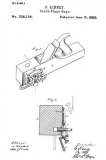
Figure 1 is a perspective view of a plane-stock with my improvement attached. Fig 2 is a vertical cross-section, showing my device adjusted to bevel the work, and in dotted lines as set to form a square, and as folded up against the side of the stock.

In the accompanying drawings, which form a part of this specification, A represents a plane-stock, to the left-hand side of which I rigidly secure a plate, B. To this plate B, I pivotally secure the angle-iron C, to the free end of which is rigidly secured the gage-plate D.

A thumb-screw, a, having a flat head, passing through the slot b in the angle-iron is tapped into a nut, c, rigidly secured in the side of the plane-stock, and a similar screw, d, is tapped through the angle-iron, as shown, the inner end of which is designed to impinge against the face of the plane. This arrangement of the adjusting-screws allows of a nicety and firmness of adjustment not usually attainable in devices of this character, without the employment of much more complicated means, because by turning out the thumb-screw a the angle of the plate D may be varied to a nicety, and by screwing in the screw d the plate is fastened in the desired position, without chance of variation, as the edges of the slot b bear on the head of the thumb-screw a and thus lock it fast, so that it will not turn accidentally or without considerable force being applied to it.

A gage constructed substantially as herein described can readily be set at right angles to the face of the plane and used for squaring the work, or it may be adjusted so as to form a bevel, care being taken that the gage-plate be held firmly against a straight side.

When desired, the device may be folded back against the side of the plane, which can then be used for all the general purposes to which a plane is put.

To fold the guide back it is only necessary to turn the screw a so that the flat side of its head will be parallel with the slot b, when the guide can be turned back out of the way, as shown in dotted lines on the upper part of Fig. 2.

What I claim as my invention is —

1. The combination of the plate B, attached to a plane, the angle-plate C D, hinged to the plate B, and having a slot, b, at right angles to the hinge, with the set-screw a passing through said slot and screwing into a nut in the plane, and the locking-screw ol bearing against the plane, substantially as and for the purpose specified.

2. In a gage for planes, the combination, with the plate B, of the hinged angle-plate C D, having a slot, b, at right angles to the hinge, and a flat-headed set-screw, a, whereby said plate D may be adjusted at any desired angle, or the plate folded back, by turning the screw a a quarter-revolution, substantially as described.

CYRUS KINNEY.

Witnesses:
H. S. SPRAGUE,
CHARLES J. HUNT.

No. 227,452 – Bench-Plane (William Steers) (1880)

[paiddownloads id=”307″]227452


UNITED STATES PATENT OFFICE.

_________________

WILLIAM STEERS, OF SHERBBOOKE, QUEBEC, CANADA.

BENCH-PLANE.

_________________

SPECIFICATION forming part of Letters Patent No. 227,452, dated May 11, 1880.
Application filed February 2, 1880.

_________________

To all whom it may concern:

Be it known that I, WILLIAM STEERS, of the city of Sherbrooke, in the Province of Quebec, in the Dominion of Canada, have invented new and useful Improvements in Metallic Planes, which improvements are fully set forth in the following specification, reference being had to the accompanying drawing.

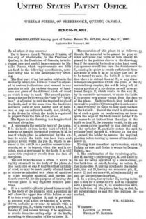
The first part of my invention relates to the device by which the knife or “iron” is adjusted to various inclinations and secured in any position to suit the various degrees of hardness and grain of the different kinds of wood on which it may be used. The second part relates to the device by which the “cap ” or “back-iron” is adjusted to suit the required angle of the knife, and at the same time the back-iron serves in place of both holder and of back-iron or cap as ordinarily used; and, thirdly, to the device by which the knife is regulated to project from the face ofthe plane.

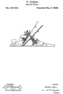
The figure in the drawing is a longitudinal sectional elevation.

A represents the metallic body of the plane. B is the knife or iron, in the back of which is a series of parallel horizontal grooves, M M, in one of which (that is determined by the extent to which the knife has been worn and ground away) works the pin E, which is secured to the nut D in a position somewhat eccentric, so as to impart, when the nut is rotated, such a movement to the knife B as will cause it to project or recede from the face of the plane.

The nut D works upon a screw, C, which is rigidly attached to the body of the plane A. The back-iron or cap F may be either entirely of steel, or may be made partly of steel fused or otherwise attached to a plate of cast-iron or other suitable material, and carries the thumb-screw G, for the purpose of locking the various parts in any required relative positions.

H is a metallic cylinder placed transversely to the body of the plane in such a position as will allow the upper face of the holder or cap F to bear evenly against it, and is provided at one end with a slot for the end of a screw-driver, and also at or near its middle with a projecting pin, K, which works in a slot, L, in the cap F, and causes the cap F to approach or recede from the cutting-edge of the knife, according to the rotation of the cylinder H.

The operation of this plane is as follows: Should the material to be planed be pine or other soft wood, the knife or iron should be placed in the position shown in the drawing; but if the material be birch or other hard wood the operator would first turn the thumb-screw G, causing its point to recede sufficiently from the knife or iron B so as to allow the nut D to be turned to raise the knife B to the position shown in dotted lines at N, or any other intermediate position which the grain of the material may require, the nut D being left at such a portion of a revolution as will have allowed the pin E, which works in the slot M, by its eccentric movement, to cause the knife B to project to a proper extent from the face of the plane. Each portion is then locked in its relative position by turning the thumb-screw G and bringing its point to bear upon the face of the knife B. Should the wood in either case be of such a grain or conformation as to require the edge of the back-iron or holder F to be nearer to or farther from the edge of the knife or iron B, the operator would, by the use of a screw-driver inserted in the slotted end of the cylinder H, partially rotate the said cylinder until the pin K, working in the slot L, caused the holder to assume the required position before locking by means ofthe thumb-screw G.

Having thus described my invention, what I claim as new, and desire to secure by Letters Patent, is —

1. The combination of the revolving cylinder H, having a projecting pin, K, and a slot in its end for being operated by a screw-driver, the back-iron or cap F, having an orifice, L, the plane-iron B, having notches in the under side, the nut D, having an eccentric pin, E, screw C, and set-screw G, all substantially as and for the purpose described.

2. In a plane, the cylinder H, having in its end a slot for a screw-driver and on its under side a projecting pin, K, in combination with the back-iron of the plane, having a slot, L, all substantially as and for the purpose described.

WM. STEERS.

Witnesses:
LOUIS S. LA BILLE,
THOMAS W. SANNER.