
No. 230,088 – Bench-Plane (William T. Wainwright) (1880)
UNITED STATES PATENT OFFICE.
_________________
WILLIAM T. WAINWRIGHT, OF DRY SAWMILL, PENNSYLVANIA.
BENCH-PLANE.
_________________
SPECIFICATION forming part of Letters Patent No. 230,088, dated July 13, 1880.
Application filed April 28, 1880. (No model.)
_________________
To all whom it may concern:
Be it known that I, WILLIAM T. WAINWRIGHT, of Dry Sawmill, in the county of Elk and State of Pennsylvania, have invented a new and useful Improvement in Planes, of which the following is a specification.
My invention consists in certain novel details of construction and arrangement of parts, whereby the same tool may be used for square-jointing, for beveling, and for rabbeting, as hereinafter particularly described.
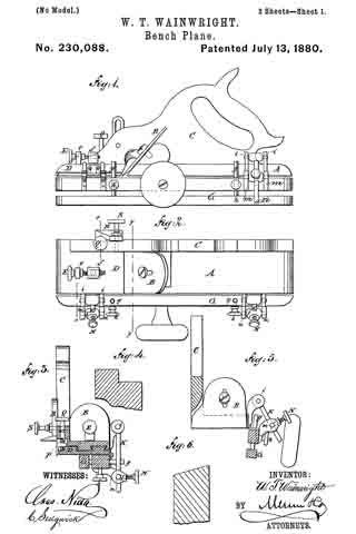
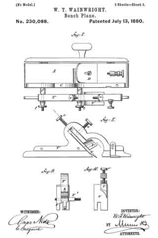
In the accompanying drawings, Figure 1 is a side view of a plane embodying my improvements. Fig. 2 is a top view of the same. Fig. 3 is a transverse vertical section taken in the line x x of Fig. 2. Fig. 5 is a transverse vertical section taken in the line y y of Fig. 2. Figs. 4. and 6 are views hereinafter referred to. Figs. 7, 8, 9, and 10 are views of grooving and tonguing attachments as applied to my plane, hereinafter referred to.
Similar letters of reference indicate corresponding parts.
The plane A, bit B, and handle C may be of the usual or any suitable description.
To the front end of the plane is attached (see Fig. 3) a block, D, which slides on tongue-and-groove dovetail ways arranged longitudinally of the plane, and may be adjusted nearer to or farther from the bit B, in order to regulate the size of the throat, by means of a thumb-screw, E, working through a standard, e, attached to the block D, and engaging with an internally-threaded standard, f attached to the plane A, and passing through a slot in the block.
To the left-hand side of the plane is hinged a bar, G, composed of two pieces connected by pins g. One end of each pin is fast to one of the pieces, and the remainder of its length is arranged to slide in a hole in the other piece transversely to a set-screw, lt, the point of which bears against the pin. By this means the bar may be widened or narrowed, to accommodate work of different widths.
To the plane A are attached two pairs of perforated lugs, i i, i i, which form bearings for lateral gudgeons extending from one end of each of two pins, K K, the remaining portion of each of which slides in a globe, l, provided with lateral gudgeons having their bearings in perforated lugs m, arranged in pairs and attached to the bar G, and each provided with a thumb-screw, N, the point of which bears against the pin K. By this means the bar G may be adjusted at an angle with relation to the plane, as shown in Fig. 5, so as to plane a bevel, as shown in Fig. 6 of the drawings, or may be adusted at any other suitable angle; and when not in use it may be folded under the plane, as shown in Fig. 3.
On the right-hand side of the plane (see Fig. 3) is a recess, in which works a cutting-blade, P, regulated by a thumb-screw, Q, working in the handle C. On the outer side of the handle is a slotted gage, B, provided with a thumb-screw, S. By means of this cutting-blade P and the plane-bit B a rabbet (such as is shown in Fig. 4) may be cut, and the depth of cut is regulated by the gage R and screw S.
Figs. 7, 8, 9, and 10 represent an attachment for making tongues and grooves. It consists of a bar, T, attached to the plane A by screw-bolts T2, provided with heads t.
The bar T carries a tonguing-bit, U, which may be changed for a grooving-bit. Both of said bits are held in place by a thumb-screw, u, which passes through a slot in the shank of a cutting-bit, V, provided with a thumb-screw, v, for adjusting it.
The bit V is intended to make a cut parallel with the line of travel of the tonguing or grooving bit and co-operate with said bit in removing the shavings. When this attachment is not in use it may be removed and laid aside by unscrewing the bolts T2.
Having thus described my invention, I claim as new and desire to secure by Letters Patent —
1. The combination, with the plane A, of the hinged bar G, lugs i and m, pins K, globes l, and screws N, fbr adjusting the plane for beveling, as herein shown and described.
2. The combination, with the plane A, of the rabbet-cutting blade P, screw Q, gage R, and screw S, as herein shown and described.
WM. TYLER WAINWRIGHT.
Witnesses:
GEORGE A. JOHNSON,
JOHN WAINWRIGHT.