
| PLEASE NOTE: The images presented on this page are of low resolution and, as a result, will not print out very well. If you wish to have higher resolution files then you may purchase them for only $2.95 per patent by using the "Buy Now" button below. All purchases are via PayPal. These files have all been cleaned up and digitally enhanced and are therefore suitable for printing, publication or framing. Each zip package contains all the images below (some packages may contain more), and purchased files can be downloaded immediately. |


UNITED STATES PATENT OFFICE.
_________________
CHARLES H. HAWLEY, OF HARTFORD, CONN., ASSIGNOR TO LEONARD BAILEY, OF SAME PLACE.
IMPROVEMENT IN BENCH-PLANES.
_________________
Specification forming part of Letters Patent No. 196,450, dated October 23, 1877; application filed October 1, 1875.
_________________
To all whom it may concern:
Be it known that I, CHARLES H. HAWLEY, of Hartford, in the county of Hartford and State of Connecticut, have invented an Improvement in Bench-Planes, of which the following is a specification, reference being had to the accompanying drawings, where —
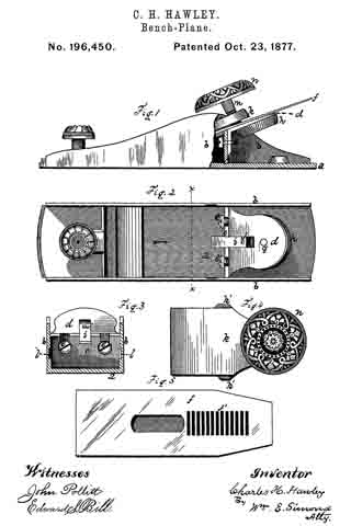
Figure 1 is a side view with a part of the side of the plane broken away. Fig. 2 is a top view, with the plane-iron and cap-plate removed. Fig. 3 is a view of the parts shown in Fig. 2 in transverse vertical section, on plane x x, looking in the direction indicated by the arrow. Fig. 4 is a top view of the cap-plate. Fig. 5 is a bottom view of the iron.
The plane is a metallic one — body, &c., of cast-iron, by preference.
The letter a denotes the floor of the plane, and b b the sides, cast in one piece with the floor; c, a transverse upright, cast in the same piece to which is secured the bed d by screws e e. On this bed lies the plane-iron f, its front end running down to the throat. Underneath the bed is hung, on pin g, the scroll-disk h, which rotates on the pin. A grooved scroll is cut into the upper face of disk h. (Partly seen in Fig. 2.) In the bed d is hung the reciprocating follower i, through which runs the pin j, fast in the follower, its lower end projecting into the scroll-groove, and its upper end projecting, when the plane-iron is in its place, into one of the transverse grooves f’, made in the under side of the plane-iron, so that the iron must then reciprocate longitudinally with the follower i. These reciprocations are given by the rotation of the scroll-disk, and the purpose thereof is to allow the fine longitudinal adjustment of the plane iron or bit.
The location of the scroll-disk just underneath the plane-iron bed is important, as it enables me to make direct connection between the scroll-disk and the iron or bit without the intervention of levers and the like, and it brings this disk into position for manipulation by the workman.
I am aware of the patent of J. A. Traut, January 16, 1877, No. 186,281, wherein the scroll-disk is applied directly to the chisel or plane-iron; but this construction is objectionable, in that the rotation of the disk moves the chisel sidewise, and makes it bind; and it also disturbs the true adjustment of the cutting-edge.
I am also aware of the patent of J. F. Baldwin, November 25, 1873, No. 144,823, which shows a slide or other device intermediate between the plane-iron or chisel and an adjusting-screw; but this construction is likewise objectionable and defective, and neither attains the same ends as a scroll for operating a plane-iron, between which is interposed a follower independent of both, but co-operating therewith.
This last-named construction is peculiar to my plane, and has marked advantages over the other, and especially in that by it I am enabled to adjust the chisel accurately and easily.
The essential feature of my invention is , thus, the independent intermediate follower, constructed and arranged as above specified.
The cap-plate is serves to secure the iron or bit in its place when adjusted. It is provided on the sides with wings k’, which slide into slots or mortises l, cut obliquely in the inner faces of the two sides of the plane-body, entering at the rear ends of these slots.
The cap-plate, when in place, acts as a lever, of which the wings k’ are the fulcra, and by turning down the screw m, the iron or bit is pinched by the front end of the cap-plate and by the screw.
This method of giving fulera has important advantages. The whole space between the sides of the body is left open and unobstructed, so that the chisel can be laid flatly down to its place without having to shove it under a cross-bar, or under lugs projecting from the sides, as has been the practice heretofore.
In these planes, which have no regular handle, it is necessary to have something to serve in the place thereof for the palm of the hand to rest upon. I attain this end by putting a semi-sphere or convex plate, a, upon the head of the screw m, which is thereby made to serve the purpose of a handle, and of a head for the screw.
I claiam as my invention —
The independent follower i, arranged between the scroll-disk and the chisel, and having pin j projecting from both sides, so as to enter the serrations f’ in the plane iron or bit f on one side, end the groove or channel in the scroll-disk h, on the other side, substantially as and for the purpose described.
CHARLES H. HAWLEY.
Witnesses:
JAMES HOLLEY,
ROALD ARENTZ.