No. 378,494 – Bench-Plane (Henry M. Clark) (1888)

No. 378,494 – Bench-Plane (Henry M. Clark) (1888)

[paiddownloads id=”428″]378494


UNITED STATES PATENT OFFICE.

_________________

HENRY M. CLARK, OF NEW BRITAIN, CONNECTICUT, ASSIGNOR TO
THE STANLEY RULE AND LEVEL COMPANY, OF SAME PLACE.

BENCH-PLANE.

_________________

SPECIFICATION forming part of Letters Patent No. 378,494, dated February 28, 1888.
Application filed July 23, 1887. Serial No. 245,046. (No model.)

_________________

To all whom it may concern:

Be it known that I, HENRY M. CLARK, a citizen of the United States, residing at New Britain, in the county of Hartford and State of Connecticut, have invented certain new and useful Improvements in Bench-Planes, of which the following is a specification.

This invention relates to improvements in the bit-adjusting mechanism of bench-planes; and the object of the improvement is to simplify the construction and to allow the several parts to be cheaply made and quickly assembled with but little fitting.

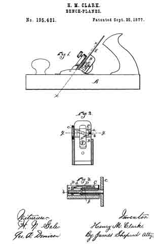
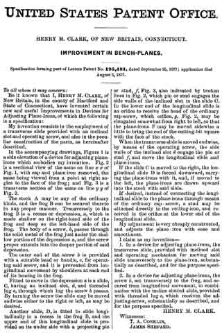
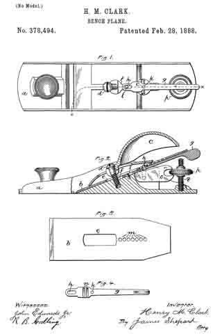
In the accompanying drawings, Figure 1 is a plan view of the stock or body of a plane of my new construction with cutting-bit and holding-cap removed. Fig. 2 is a vertical section of said plane on line x x of Fig. 1. Fig. 3 is a plan of the cutting-bit, and Fig. 4 an under side view of the lever by means of which said bit is moved laterally to square its cutting-edge with the stock.

The arrangement of the devices by means of which I effect both a lateral and longitudinal adjustment of the bit is believed to be new and forms an essential feature of my invention. Heretofore, so far as I know, the mechanism for adjusting the bit longitudinally has been connected directly with the cutting-bit or its cap-iron. In my improvement the lever for lateral adjustment forms the means of connecting the bit with the longitudinal adjustment, and thereby constitutes an essential part of said longitudinal adjustment.

In the drawings, a indicates the stock of the plane; b, the cutting-bit; c, the holding-cap, and d the screw provided for locking the cap and bit in their respective positions, the parts thus far named being old and well known. The solid portion,or so-called “frog,” of the stock a is inclined on its upper face at a proper angle to produce a shaving cut of the bit b, which bit rests on said frog at its lower end, and is slotted, as at e, to allow said bit to move both laterally and lengthwise without engaging the cap-screw d. That portion of the frog which is designed to receive the lever g is cut down, as at f, so that when the parts are assembled said lever lies underneath the bit with its upper surface in line with the forward part of the frog. The inner end of said lever is provided with a slot, h, which straddles a pin, i, projecting from the frog, said slot and pin forming a floating fulcrum for said lever. Between said fulcrum and the free end of lever g is a pivot-pin, k, projecting upward from said lever, and adapted to enter any one of a series of holes, m, in bit b.

Assuming, now, that we have a plane of the construction thus far described, the lateral movement of lever g in either direction will move the cutting-bit b (in the same direction) a distance proportionate to the leverage provided. In order to add to said construction mechanism for moving the bit longitudinally to govern the depth of the cut, I have provided transverse recesses or grooves n in the under side of lever g, and have connected therewith a toothed plate, o, pivoted in the stock a, and actuated by a thumb-nut, p, on a fixed screw, q. This device in itself is well known and needs no detailed description, and other known mechanism for longitudinal adjustment may be substituted therefor. It will now be understood that when it is desired to increase the depth of out the turning of thumb-nut p to the left hand will elevate the forked end of the plate o, and thus move forward lever g and the cutting-bit, to which said lever is attached by pin k.

Lever g is allowed to move lengthwise a considerable distance by the fulcrum-slot h, and as the bit becomes worn and shortened pin k may be entered in the next hole, m, of the series. To adjust bit b laterally to square its cutting-edge with stock a, the free end of lever g is swung to one side, as above noted, the action being the same as in planes of this class now in common use. When said lever is thus moved laterally, the recesses or grooves n, being of considerable length, remain in engagement with the teeth of plate o, so that the bit may be adjusted longitudinally without adjusting it laterally, or vice versa.

I am aware that a prior patent for a bench-plane shows and describes an adjusting-screw connected to and operating a longitudinally-sliding block that is clamped to the under side of the cutting-bit by a screw which passes through a fellow plate on the upper side of the cutting-bit and through the slot in said bit, which block, fellow plate, and screw form the sole means of connecting the adjusting-screw with the cutting-bit. The said sliding block and fellow plate have connected thereto a laterally-adjusting lever, the same being carried longitudinally with said block and fellow plate. Such a plane, having a laterally-adjusting lever which merely rides upon the mechanism for adjusting the cutting-bit longitudinally without forming an essential part of said longitudinal adjusting mechanism, is hereby disclaimed.

I claim as my invention —

1. In a bench-plane, the combination of the laterally-adjusting lever, the mechanism for operating directly upon said lever for adjusting it longitudinally, and the cutting-bit connected to said laterally-adjusting lever, whereby said lever forms an essential part of the mechanism for adjusting the cutting-bit longitudinally, substantially as described, and for the purpose specified.

2. In a bench-plane, the combination of the cutting-bit having a series of holes, m, the laterally-adjusting lever let into the face of the frog and fulcrumed thereon by a pin-and-slot connection, said lever also having a pin for insertion in one of the holes m, and mechanism applied directly to said lever for adjusting it, and through it the bit in a longitudinal direction, substantially as described, and for the purpose specified.

HENRY M. CLARK.

Witnesses:
JOHN EDWARDS, Jr.,
JAMES SHEPARD.

No. 195,481 – Improvement In Bench-Planes (Henry M. Clark) (1877)

[paiddownloads id=”283″]195481


UNITED STATES PATENT OFFICE.

_________________

HENRY M. CLARK, OF NEW BRITAIN, CONNECTICUT.

IMPROVEMENT IN BENCH-PLANES.

_________________

Specification forming part of Letters Patent No. 195,481, dated September 25, 1877; application filed August 6, 1877.

_________________

To all whom it may concern:

Be it known that I, HENRY M. CLARK, of New Britain, in the county of Hartford and State of Connecticut, have invented certain new and useful Improvements in Devices for Adjusting Plane-Irons, of which the following is a specification:

My invention consists in the employment of a transverse slide. provided with an inclined slot and operating screw, and also in the peculiar construction of the parts, as hereinafter described.

In the accompanying drawings, Figure 1 is a side elevation of a device for adjusting plane-irons which embodies my invention. Fig. 2 is a sectional view of the same on line x x of Fig. 1, with cap and plane-iron removed, the same being viewed from a point at right angles to the face of the frog; and Fig. 3 is a transverse section of the same on line y y of Fig. 2.

The stock A may be any of the ordinary kinds, and the frog B can be secured thereto in any proper manner. Transversely to the frog B is a recess or depression, a, which is made shallow on the right-hand side of the frog and deep on the left-hand side of the frog. The body of a screw, b, passes through the solid metal of the frog just under the shallow portion of the depression a, and the screw proper extends into the deeper portion of said depression.

The outer end of the screw b is provided with a suitable head or handle, c, for operating said screw, and it is prevented from longitudinal movement by shoulders at each end of its bearing in the frog.

Fitted to move in the depression a is a slide, C, having an inclined slot, d, and threaded lug e, through which lug the screw b passes. By turning the screw the slide may be moved endwise either to the right or left, as may be desired.

Another slide, D, is fitted to slide longitudinally in a recess in the frog B, and the upper end of this longitudinal slide is provided on its under side with a projecting pin or stud, f Fig. 3, also indicated by broken lines in Fig. 2, which pin or stud engages the side walls of the inclined slot in the slide C. In the lower end of the longitudinal slide is an orifice to receive the head of the ordinary cap-screw, which orifice, g, Fig. 2, may be elongated somewhat from right to left, so that the plane-irons F may be moved sidewise a little to bring the end of the cutting-bit square with the face of the stock.

When the transverse slide is moved endwise, by means of the operating screw, the side walls of the inclined slot d engage the pin or stud f and move the longitudinal slide and plane-irons.

If the slide C is moved to the right, the Iongitudinal slide D is forced downward, carrying the plane-irons with it, and, if moved to the left, the plane-irons are drawn upward into the stock with said slide.

If desired, instead of connecting the longitudinal slide to the plane-irons through means of the ordinary cap-screw, a stud may be attached directly to the cutting-iron, and received in the orifice at the lower end of the longitudinal slide.

My adjustment is very cheaply constructed, and adjusts the plane-iron with ease and smoothness.

I claim as my invention —

1. In a device for adjusting plane-irons, the transverse slide, provided with inclined slot and operating mechanism for moving said slide transversely to the plane-iron, substantially as described, and for the purpose specified.

2. In a device for adjusting plane-irons, the screw b, set transversely to the frog, and secured from longitudinal movement, in combination with the incline slotted slide, provided with threaded lug e, which receives the adjusting-screw, substantially as described, and for the purpose specified.

HENRY M. CLARK.

Witnesses:
T. A. CONKLIN,
JAMES SHEPARD.

No. 195,480 – Improvement In Circular Planes (Henry M. Clark) (1877)

[paiddownloads id=”282″]195480


UNITED STATES PATENT OFFICE.

_________________

HENRY M. CLARK, OF NEW BRITAIN, CONNECTICUT, ASSIGNOR TO THE STANLEY RULE AND LEVEL COMPANY, OF SAME PLACE.

IMPROVEMENT IN CIRCULAR PLANES.

_________________

Specification forming part of Letters Patent No. 195,480, dated September 25, 1877 application filed August 6, 1877.

_________________

To all whom it may concern:

Be it known that I, HENRY M. CLARK, of New Britain, in the county of Hartford and State of Connecticut, have invented certain new and useful Improvements in Circular Planes, of which the following is a specification:

My invention consists of a connecting mechanism for the two ends of the flexible bottom of a circular plane, so that they necessarily move together, in combining therewith a single operating device, in the peculiar construction of parts, and in their combination, as hereinafter described.

In the accompanying drawings, Figure 1 is a side elevation of a circular plane, which embodies my invention. Fig. 2 is a vertical section of the same on line y y of Fig. 3, and Fig. 3 is a horizontal section of the same on line x x of Fig. 2.

In Fig. 1 the flexible bottom A is set in a convex position for dressing a concave surface, and in Figs. 2 and 3 it is set in a concave position for dressing a convex surface.

Circular planes having a flexible bottom and mechanism for holding the same when set in various circles are old; but, so far as I know, the two ends of the flexible bottom have never before been so connected as to necessitate their simultaneous movement. These prior planes had no mechanism for moving the ends of the flexible bottom, but only mechanism for holding the ends in place when moved by hand; and these holding mechanisms were entirely independent of each other, so that unless great care was taken in setting the bottom, one end would be bent to conform to one sized circle and the other end to conform to a circle of a different size.

The object of my invention is to adjust the flexible bottom more conveniently than heretofore, and to always adjust both ends to the same circle.

The flexible bottom A is secured to the stock B by screws taking into the stock at each side of the throat, in the usual manner of securing the same in circular planes.

At one side of the stock B short shafts a a are secured in proper bearings, so as to partially rotate therein. On the inner ends of said shafts a a, and in the middle of the stock B, rocking levers C C are rigidly secured, so as to rotate with said shafts. The outer ends of the rocking levers C C are connected to the ends of the flexible bottom A by means of the links b b.

On the outer ends of the shafts a a, rigidly secured, are segment-gears c c, which mesh into each other and necessitate the movement of one shaft with its fellow.

Inasmuch as the rear end of the flexible bottom is longer than its front end, and describes a larger circle in bending, the segment-gear on the front or short end is made larger than the segment-gear on the long end, in order to cause the latter to move enough faster than the former to compensate for the difference in the size of the circle described by the two ends of the flexible bottom.

In the front end of the stock B there is a rocking block or nut, d, which receives the adjusting-screw e, surmounted by a suitable knob or handle, D. The screw e is also provided with an internal thread, running in the opposite direction from that of its external thread, which internal thread receives the adjusting-screw e’, the lower end of which is connected by a pin or other jointed connection to one of the levers.

By turning the adjusting-screw e e’, the lever C, to which it is connected, is either depressed or lowered, according to which way the screw is turned, thereby partially rotating the shaft a. The segment-gear on the outer end of the shaft, meshing into a like gear on its fellow shaft, carries the opposite lever with the one connected to the screw, and the ends of the flexible bottom being connected by the links to said levers, as shown, must necessarily move together; and if the size of the segment-gears is properly arranged in relation to the circles described by both ends of the flexible bottom, said ends will both of them always be bent to conform to the same circle under all the various adjustments which they undergo.

The double screw e e’ is merely for the purpose of increasing the motion of the lever, and may, if desired, be omitted, and a single screw substituted therefor.

Other means might be employed for moving the levers or securing them in place without changing the portion of the invention which relates to moving both ends of the flexible bottom together.

If desired, the segment-gears might be separated a little and a worm placed between them, so as to engage the teeth thereof, whereby turning the worm will simultaneously move both segment-gears, levers, &c., in either of which modifications a single handle only has to be manipulated to operate both ends of the flexible bottom.

I claim —

1. In a circular plane, the combination of the flexible bottom A and mechanism, substantially as described, connecting its two ends, for necessitating their simultaneous movement, substantially as described.

2. In a circular plane, the combination of the flexible bottom A, mechanism, substantially as described, connecting its two ends and necessitating their simultaneous movement, and a single adjusting or operating handle, substantially as described, and for the purpose specfiied.

3. In a circular plane, the combination of the stock B, flexible bottom A, link b, rocking lever C, and adjusting-screw e, substantially as described, and for the purpose specified.

4. In a circular plane, the combination of the flexible bottom A, links b b, levers C C, shafts a a, and sement-gears c c, substantiallly as described, and for the purpose specified.

HENRY M. CLARK.

Witnesses:
T. A. CONKLIN,
JAMES SHEPARD.