No. 272,274 – Stop Chamfer Plane (Joseph Lee) (1883)

UNITED STATES PATENT OFFICE.
_________________
JOSEPH LEE, OF GARNERVILLE, NEW YORK, ASSIGNOR OF ONE-THIRD TO RICHARD FISHWICK, OF SAME PLACE.
STOP CHAMFER PLANE.
_________________
SPECIFICATION forming part of Letters Patent No. 272,274, dated February 13, 1883.
Application filed August 12, 1882. (No model.)
_________________
To all whom it may concern:
Be it known that I, JOSEPH LEE, of Garnerville, in the county of Rockland and State of New York, have invented a new and Improved Stop Charnfer Plane, of which the following is a full clear, and exact description.
The object of my invention is to facilitate the cutting of chamfers of all kinds on the edges of posts, boards, &c.
The invention consists in a stop chamfer plane formed of two parallel bevel-guides united by adjustable cross rods, and carrying a cutting-blade which can be locked in position by a binding-screw.
The invention also consists in a transverse gage for facilitating the adjustment of the implement.
The invention also consists in the construction of details and in the combinations of parts, as will be more fully described hereinafter.
Reference is to be had to the accompanying drawings, forming part of this specification, in which similar letters of reference indicate corresponding parts in both the figures.
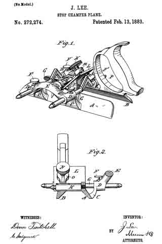
Figure 1 is a perspective view of my improved stop chamfer plane. Fig. 2 is a cross-sectional elevation of the same.
The plane is composed of two beveled guides, A and B, which are parallel lengthwise, but have their sides inclined toward each other at right angles. The guide A is provided with two upwardly-projecting lugs, C, terminating in eyes D, united by a curved handle-piece, E. The eyes D are provided with binding-screws F. The beveled guide B is provided with upwardly-projecting lugs terminating in eyes D’, provided with binding-screws F’. Two cross-rods, G, each provided near one end with a V shaped bend, are passed through the eyes D D’, and can be locked in the desired position in the same by means of the screws F F’. A graduated transverse arm or gage, H, projects from the upper edge of the guide A, and passes through an eye or loop, J, on the upper edge of the bevel-guide B. The guides A and B are provided with triangular ridges or projections K K’ on the upper edges, the under edges of these ridges projecting downward from the rear toward the front of the plane. The triangular projection K’ has a wide upper edge, and the edge of the projection K is very narrow. The cutting-blade L is placed on the ridges K K’, and is provided along one edge with a groove, M, adapted to receive the upper edge of the ridge K on the guide A. A binding-screw, N, held on the upper end of an inclined lug, O, above the inclined ridge K’, binds and holds the cutting-blade L on the ridges K K’. The guide B is provided at its rear end with a handle, P, of the usual construction. The cutting-edge of the blade L passes into notches a in the upper edges of the guides A and B. According to the desired width of the chamfer, the guides A and B are adjusted a greater or less distance from each other, the said adjustment being facilitated by the gage H, and then the blade L is held in place by means of the binding-screw N. The inner surfaces of the guides A and B rest against the sides of the board or post to be chamfered. Plain or molded or beaded chamfers can be cut, a cutting-blade with a corresponding cutting-edge being held in the implement for the desired charnfer. Chamfers running the whole length of the edge of the board, or stop-chamfers, which stop a greater or less distance from the ends of the board or post, can be cut by means of the above described implement. The handle piece E greatly facilitates adjusting the instrument. In operating the instrument one hand holds the handle P and the other is rested on the handle E.
Having thus described my invention, I claim as new and desire to secure by Letters Patent —
1. A stop chamfer plane having two parallel and relatively-adjustable bevel-guides with sides inclined at a right angle to each other, in combination with mechanism for holding said guides in their relative positions, as shown and described.
2. The combination of the guides A B, provided with upwardly-projecting lugs carrying eyes D D’, the curved piece E, connecting eyes D and the binding-screws F F’, with the two cross-rods G G, having V-shaped bends, passing through said eyes, and adapted to be locked in any desired position, as described.
3. The combination, with the adjustable guides A B, of the gage H, projected from the upper edge of guide A, and passing through a loop. J, of the guide B, as shown and described.
4. The combination, with the guides A B, having notches a in their upper edges, the triangular ridges K K’, and the inclined lug O, of a cutting-blade, L, having edge-groove M and binding-screw N, as and for the purpose specified.
JOSEPH LEE.
Witnesses:
WILLIAM MAYBURY,
WM. P. BANIGAN.


