
No. 271,569 – Bench-Plane (David A. Bridges) (1883)
No. 271,569 – Bench-Plane (David A. Bridges) (1883)
UNITED STATES PATENT OFFICE.
_________________
DAVID A. BRIDGES, OF VINELAND, NEW JERSEY, ASSIGNOR OF THREE-FOURTHS TO JOHN GAGE, OF SAME PLACE.
BENCH-PLANE.
_________________
SPECIFICATION forming part of Letters Patent No. 271,569, dated January 30, 1883.
Application filed April 17, 1882. (No model.)
_________________
To all whom it may concern:
Be it known that I, DAVID A. BRIDGES, a citizen of the United States, and a resident of Vineland, Cumberland county, and State of New Jersey, have invented certain Improvements in Bench-Planes, of which the following is a specification.
The object of this invention is to provide an efficient bench-plane which can be adjusted with perfect ease to its work; and the invention consists mainly in providing fixed bearings in the stock or throat-iron for the cap-plate, and adjusting the bit independently thereof, in the construction and novel arrangement of the parallel-sided throat-iron or bit-holder having the wear-face, in the construction and novel arrangement of the transverse bit-clamp forming the bearing which engages the adjusting-screw, in the combination of the adjusting-screw with the bit-holder and wear-plate, these being formed entire, and in the construction and novel arrangement of the base-plate of the handle let into a recessed and depressed seat in the rear of the stock, all as hereinafter set forth.
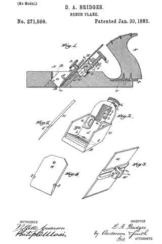
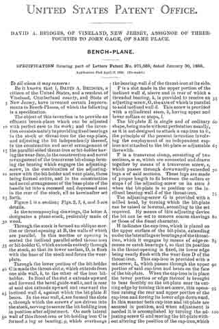
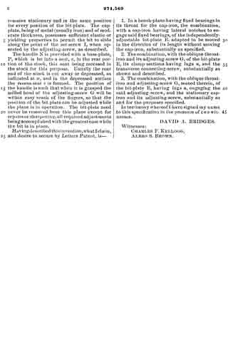
Figure 1 is a section; Figs. 2, 3, 4, and 5 are details.
In the accompanying drawings, the letter A designates a plane-stock, preferably made of wood.
Through the stock is formed an oblique mortise or throat-opening at B, the walls of which are parallel. In this mortise or opening is seated the inclined parallel-sided throat-iron or bit-holder G, which extends entirely through the stock, so that its lower surface, D, is flush with the base of the stock and forms the wear-plate.
Through the lower portion of the bit-holder C is made the throat-slot a, which extends from one side wall, b, to the other of the iron bit-holder. In front of the slot a extends upward and forward the bevel guide-wall c, and in rear of said slot extends upward and rearward the inclined wall d, against which the bit-plate E bears. In the rear wall, d,are formed the slots c, through which the screws e’ are driven into the stock, serving to secure the bit-holding iron in position after adjustment. On each lateral wall of this throat-iron or bit-holding iron C is formed a lug or bearing, g, which overhangs the bearing-wall d of the throat-iron at its side.
F is a slot made in the upper portion of the inclined wall d, above and in rear of which a threaded bearing, h, is provided to receive an adjusting-screw, G, the axis of which is parallel to said inclined wall d. This screw is provided with a cylindrical stem, k, having upper and lower collars or stops, l.
The bit-plate E is single and of ordinary shape, being made without perforation usually, as it is not designed to attach a cap-iron to it, the principle of the present invention involving the employment of an independent cap-iron not attached to the bit-plate or adjustable therewith.
F is a transverse clamp, consisting of two sections, m m, which are connected and drawn together by means of a transverse screw, s, which passes through downwardly-extended lugs it of said sections. These lugs are made of proper length to fit between the collars or stops l of the adjusting-screw on its stem k when the bit-plate is in position on the inclined bearing-wall d of the throat-iron.
The adjusting-screw G is provided with a milled head, by turning which the bit-plate can be raised or lowered, according to the set required. By means of this adjusting device the bit can be set to remove coarse shavings or those of the finest character.
H indicates the cap-iron, which is placed on the upper surface of the bit-plate, extending under the lateral lugs or bearings g of the throat-iron, which it engages by means of edge-recesses or catch-bearings t, so that its position in the throat-opening is fixed, its lower edge being nearly flush with the wear-face D of the throat-iron. This cap-iron is provided with a set-screw, L, which passes through the upper portion of said cap-iron and bears on the face of the bit-plate. When the cap-iron is in place the lower portion or edge thereof is brought to bear forcibly on the bit-plate near its cutting-edge by turning this set-screw, this operation raising the rear and upper portion of the cap-iron and forcing its lower edge downward. In this manner both cap-iron and bit-plate are secured in position, and when adjustment is needed it is accomplished by turning the adjusting-screw G and moving the bit-plate without altering the position of the cap-iron, which remains stationary and in the same position for every position of the bit-plate. The cap-plate, being of metal (usually iron) and of moderate thickness, possesses sufficient elastic or yielding properties to permit the bit to slide along the point of the set-screw I, when operated by the adjusting-screw, as described.
The handle N is provided with a base-plate, P, which is let into a seat, v, in the rear portion of the stock, this seat being recessed in the stock for this purpose. Usually the rear end of the stock is cut away or depressed, as indicated at w, and in the depressed surface the recess-seat in is formed. The position of the handle is such that when it is grasped the milled head of the adjusting-screw G will be within easy reach of the fingers, so that the position of the bit plate can be adjusted while the plane is in operation. The bit-plate need never be removed from this plane except for repairs or sharpening, all required adjustments being accomplished with the greatest ease while the bit is in place.
Having described this invention what l claim, and desire to secure by Letters Patent, is —
1. In a bench-plane having fixed bearings in its throat for the cap-iron, the combination, with a cap-iron having lateral notches to engage said fixed bearings of the independently-adjustable bit-plate E, adapted to be moved in the direction of its length without moving the cap-iron, substantially as specified.
2. The combination, with the oblique throat-iron and its adjusting-screw G, of the bit-plate E, its clamp sections having lugs n, and the transverse connecting-screw, substantially as shown and described.
3. The combination, with the oblique throat-iron and adjusting-screw G, seated therein, of the bit-plate E, having lugs n, engaging the said adjusting-screw, and the stationary cap-iron and its adjusting-screw, substantially as and for the purposes specified.
In testimony whereof I have signed my name to this specification in the presence of two witnesses.
DAVID A. BRIDGES.
Witnesses:
CHARLES F. KELLOGG,
ALBRO S. BROWN.