
No. 271,219 – Bench-Plane (John Campbell) (1883)
UNITED STATES PATENT OFFICE.
_________________
JOHN CAMPBELL, OF WALDEN, NEW YORK.
BENCH-PLANE.
_________________
SPECIFICATION forming part of Letters Patent No. 271,219, dated January 30, 1883.
Application filed August 9, 1882. (No model.)
_________________
To all whom it may concern:
Be it known that I, JOHN CAMPBELL, of Sheffield, England, and a resident of Walden, in the town of Montgomery, in the county of Orange and State of New York, have invented certain new and useful Improvements in Planes; and I do hereby declare the following to be a full, clear, and exact description of the invention, such as will enable others skilled in the art to which it pertains to make and use the same.
My invention relates to planes, the object being to provide a plane adapted for use either as a chamfer or smoothing plane, of such construction as to be readily adjusted.
The invention consists in the peculiar construction and combinations of parts hereinafter described, and pointed out in the claim.
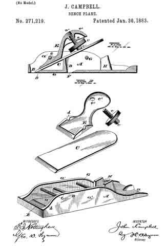
In the drawings, Figure 1 represents a perspective view of my improvement, and Fig. 2 is a view of the parts detached.
A represents the stock of the plane, consisting of the sole a and sides a’ a’. The sole is provided at its forward end with a slot, B, and beveled seat b for the point of the bit. The bit or plane-iron C is adapted to project under a rod, c, set into the sides of the stock, and to rest on a beveled bed or rest, D. A wedge, E, is then forced under the rod c, and is held in place by a screw, e, provided with a disk or head, e’, which bears against the upper end of the bit. The upper end of the wedge E is rounded and curved to form a bearing, e2, for the hand or fingers, and is provided with a central screw-threaded perforation, e3, adapted to receive the screw e. This wedge E is also provided with upwardly-projecting side ears, d, which latter are centrally grooved for the purpose of preventing the wedge from rising up when secured in place. When the wedge is unscrewed, the bit is firmly clamped, while by turning the screw into the perforation of the wedge the bit is loosened and may be removed.
The sole a of the stock is provided with a second slot, F, just in rear of the rest D, while a rod, G, is secured between the sides in rear of the slot F, and two projecting beveled rests, H, are provided adjacent to the rod. Thus it will be seen that the bit may be secured at the forward end of the stock to form a chamfer-plane, or at the center to form a smoothing-plane.
The parts are simple in construction, easily manipulated, and adapted to be durable and efficient in use.
Having fully described my invention, what I claim as new, and desire to secure by Letters Patent, is —
The combination, with the stock provided with two transverse slots, one of which latter is situated near the extreme front end thereof, the beveled rests D and H, and the transverse rods c and G, of the removable bit, the wedge E, having the slotted, side ears, d, and the fastening-screw, all of the above parts combined and adapted for the purpose set forth.
In testimony whereof I have signed this specification in the presence of two subscribing witnesses.
JOHN CAMPBELL.
Witnesses:
W. G. RUTHERFORD,
W. C. STEVENS.