No. 266,519 – Carpenter’s Plow (Frank A. Rappleye) (1882)

UNITED STATES PATENT OFFICE.
_________________
FRANK A. RAPPLEYE, OF KENDAIA, NEW YORK, ASSIGNOR TO THE STANLEY RULE AND LEVEL COMPANY, OF NEW BRITAIN, CONNECTICUT.
CARPENTER’S PLOW.
_________________
SPECIFICATION forming part of Letters Patent No. 266,519, dated October 24, 1882.
Application filed February 15, 1882. (No model.)
_________________
To all whom it may concern:
Be it known that I, FRANK A. RAPPLEYE, of Kendaia, in the county of Seneca and State of New York, have invented certain new and useful Improvements in Carpenters’ Plows, of which the following is a specification.
My invention relates to improvements in convertible carpenter’s plow and slitting-tool having an attachable and detachable slitting-knife located upon one side of the bottom face of the stock and a fence upon the opposite side of said face; and the objects of my invention are to produce a readily-convertible plow and slitting-tool at a trifling cost over that of an ordinary plow, and to gage and regulate the depth of cut ofthe slitting-knife by means of the bottom face of the stock coming into contact with the top face of the strip severed by the slitting-knife. I attain these objects by the mechanism illustrated in the accompanying drwaings in which —
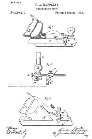
Figure 1 is a side elevation. Fig. 2 is an end view, and Fig. 3 is a side elevation of substantially the same tool in a somewhat different form.
The stock A, handles B B, and adjustable fence C may be the same as in any ordinary plow. It is essential, however, that the fence C shall be adjustable to and from the stock A and capable of being secured in position parallel to the stock, and, as shown in Fig. 2, it should project downward below the bottom edge or face of the stock A.
The patent to Justus A. Traut, of March 4, 1873, shows one good form of a plow-stock and fence; but other plows may be employed, if desired. At one side of the stock A, and near its forward end, is a. vertical socket having transverse set-screws a, within which socket I place the shank b of the slitting-knife D, which knife is a thin blade rounded and sharpened on its forward edge. This knife may be adjusted in its socket or seat, so as to make its point or lower end project any desired distance below the bottom face of the stock A, and when so adjusted it may be firmly held in place by means of the set-screw a. By means of said set-screw and socket the knife is made an attachable and detachable one.
When this plow is to be used for slitting boards or other stock into strips the ordinary plow-bit is removed from the stock A and the slitting-knife adjusted to cut the desired depth by projecting it the desired distance from the bottom face of the stock A. The fence C is also set a distance from the knife D equal to the width of the desired strip. The instrument is then placed with the fence C against one edge of the board to be slit and with the knife over one face of the board, as shown in Fig. 2, said board being indicated therein by broken lines. By bearing down upon the forward end of the plow-stock and forcing it along over the board, substantially as in plowing, the knife can readily be forced into the board until the bottom face of the stock A comes in contact with the face of the board and prevents the slitting-knife from cutting any deeper, thus making the ordinary plow-stock A serve as a depth-gage by its bottom face coming in contact with the upper face of the strip slit off. The stock being close to the knife D, and between said knife and the fence, it can always serve as a depth-gage, even when the piece to be slit is but a hair wider than the distance between the slitting-knife D and the fence C.
In Fig. 3 the slitting-knife D’ is in the form of a flat slotted blade, and the seat which supports said body is in the form of a vertical slot or open socket made in one side of the stock A. A bolt passes from the stock through the slot in the body of the knife, and a set-nut, a’, on said bolt holds the knife in position when once adjusted. The operation is the same as that of the parts shown in Figs. 1 and 2, and hereinbefore described.
It will be noticed that in both forms of knives the fence is upon one side of the stock A and the knife is upon the opposite side.
The additional cost of this improved tool over that of the ordinary plow is much less than the cost of a special slitting-tool, while it is also much more convenient to have the plow convertible into a slitting-tool than it is to use two different tools for plowing and slitting.
I am aware that marking and slitting gages of various styles have been used for slitting boards when the knife or marker was mounted in a stock or frame of its own; also, that a scoring knife or spur has been employed in planes and set between the stock and the fence to prepare the way for the planing-knife, and I hereby disclaim the same.
I claim as my invention —
The convertible plow and slitting-tool, substantially as hereinbefore described, consisting of the plow-stock A, adapted for the attachment and detachment of the ordinary plow-bit, the slitting-knife D, secured to one side of said stock, and the fence C, secured to the opposite side, the bottom face of said stock being between the fence and knife, the latter extending downward from the lower outside corner of the stock, substantially as described, and for the purpose specified.
FRANK A. RAPPLEYE.
Witnesses:
MICHAEL ROAN,
BUEL WILBUR.


