
No. 258,988 – Bench-Plane (William S. Case) (1882)
UNITED STATES PATENT OFFICE.
_________________
WILLIAM S. CASE, OF NEW BRITAIN, CONNECTICUT.
BENCH-PLANE.
_________________
SPECIFICATION forming part of Letters Patent No. 258,988, dated June 6, 1882.
Application filed March 17, 1882. (No model.)
_________________
To all whom it may concern:
Be it known that I, WILLIAM S. CASE, of New Britain, in the county of Hartford and State of Connecticut, have invented certain new and useful Improvements in Bench-Planes; and I do hereby declare that the following is a full, clear, and exact description thereof, whereby a person skilled in the art can make and use the same, reference being had to the accompanying drawings, and to the letters of reference marked thereon.
Like letters in the figures indicate the same parts.
My improvement relates to a new mechanism for adjusting the iron of a bench-plane to a greater or less depth of cut; and its object is to provide a simpler and cheaper device than has heretofore been in use for this purpose, and at the same time one which can be readily and easily operated.
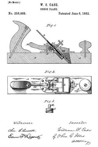
In the accompanying drawings illustrating my invention, Figure 1 is a longitudinal vertical section through the middle of the plane. Fig. 2 is a top view with the plane-iron removed so as to show the working parts. Fig. 3 is a front view of the cam which operates the lever which moves the plane-iron up or down.
A is the stock of an ordinary plane furnished with a handle and knob in the customary manner.
B is the bit, and C the cap, of the plane-iron. The bit and cap are held together by means of the screw D, which screws into the cap and moves in a slot in the bit to adjust the position of the two parts in the customary manner.
E is a metallic plate attached to the stock A, for the purpose of holding the working parts of the plane.
The plane-iron is held in place by the wedge F, which passes under the bar G, and is provided with a set-screw, H, which clamps the plane-iron against the bearings E’ and the back of the bottom of the slot in the stock.
J is a forked lever turning upon a pin, K, passing through lugs upon the plate E. The forward end of this lever is single. It passes through the slot in the bit B and enters a hole or notch in the cap C. The rear end of this lever is forked, and embraces a swinging cam, L, upon the rocking lever M.
M is a lever swinging laterally upon the pin N, by which it is attached to the plate E. Upon its front side is the cam L for operating the lever J, one of the forks of the said lever resting on the top and the other on the bottom of the cam. The movement of the lever M to the right or left raises or lowers the plane-iron, so that its edge will project more or less through the throat of the plane to adjust it to different degrees of depth in the cut. When the rear end of the lever M is pushed to the right it depresses the rear of the lever J and raises its forward end. This lifts the cap and carries with it the bit. To lower the bit the rear of the lever M is pushed to the left, which reverses the movements above described.
What I claim as my invention is —
In a bench-plane, the combination of the laterally-swinging lever M, provided with the cam L and the vertically-swinging forked Iever J, pivoted to the plate or frame E, with the said plate and the plane-iron, substantially as described.
WILLIAM S. CASE.
Witnesses:
EDWIN F. DIMOCK,
THEO. G. ELLIS.