

| PLEASE NOTE: The images presented on this page are of low resolution and, as a result, will not print out very well. If you wish to have higher resolution files then you may purchase them for only $2.95 per patent by using the "Buy Now" button below. All purchases are via PayPal. These files have all been cleaned up and digitally enhanced and are therefore suitable for printing, publication or framing. Each zip package contains all the images below (some packages may contain more), and purchased files can be downloaded immediately. |

UNITED STATES PATENT OFFICE.
_________________
WILLIAM E. SPARKS, OF NEW HAVEN, CONNECTICUT, ASSIGNOR TO SARGENT & COMPANY,
OF NEW HAVEN, CONNECTICUT, A CORPORATIGN OF CONNECTICUT.
PLANE.
_________________
1,164,232. Specification of Letters Patent. Patented Dec. 14, 1915.
Application filed July 9, 1913. Serial No. 778,083.
_________________
To all whom it may concern:
Be it known that I, WILLIAM E. SPARKS, a citizen of the United States, residing in the city and county of New Haven and State of Connecticut, have invented certain new and useful Improvements in Planes, of which the following is a full, clear, and exact description.
This invention relates to planes, and more especially to planes constructed wholly of metal.
One of the primary objects of the invention is to provide a light, strong, durable and inexpensive plane, wherein the stock or frame, the frog, and the clamp for the cutter are constructed of sheet metal. To this end the parts mentioned are of novel form and are combined and assembled in a novel way.
Another object of the invention is the provision of certain improved features of construction in what is known as a low angle block plane, more particularly the mechanism for giving the bit or cutter its lengthwise adjustment, and the location of such adjusting means in such a position that the head of the adjusting screw for the cutter serves as a palm rest when the plane is in use.
However, although my improvements are of particular advantage in low angle block planes and in planes constructed for the most part of sheet metal, certain features will be found advantageous in planes of other types.
To these and other ends, the invention consists in the novel features and combinations of parts to be hereinafter described and claimed.
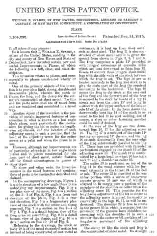
ln the accompanying drawings, Figure 1 is a side elevation of a low angle block plane embodying my improvements, Fig. 2 is a top plan view of the same, Fig. 3 is a section on line 3–3 of Fig. 2, Fig. 4 is a front end elevation of the plane, Fig. 5 is a rear end elevation, Fig. 6 is a fragmentary plan view of the stock with the cutter and clamp removed, Fig. 7 is a section on line 7–7 of Fig. 1, Fig. 8 is a detail bottom view of the frog prior to assembling, Fig. 9 is a detail bottom view of the clamp, and Fig. 10 is a detail section on line 10–10 of Fig. 2.
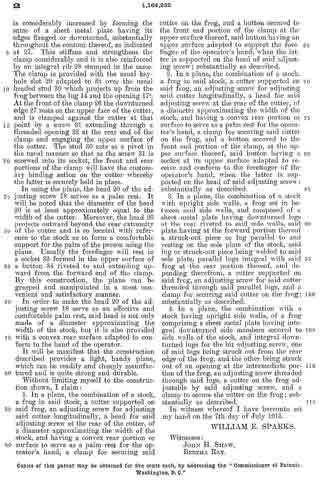
Referring to the drawings, the stock or body 10 is of the usual channeled section but instead of being constructed of cast metal as customary, it is bent up from sheet metal such as sheet steel. The frog 11 is also constructed of sheet metal and it is given the special form shown in Figs. 3, 6, 7 and 8. The frog comprises a plate 11a provided with integral extensions at opposite sides which are bent downward to form legs 12. Rivets 13 connect these integral sheet metal legs with the side walls of the stock between which the frog is set. The legs 12 are so located relatively to the frog and stock as to give the main part of the frog the required inclination to the horizontal. The legs 12 secure the frog to the stock at the rear end of the frog and the forward end of the frog is secured to the stock by means of a lug 14 struck out from the plate 11a and lying in contact with the upper surface of the bed or sole 15 of the plane. In the form shown the downwardly bent lug 14 of the stock is secured to the bed 15 by spot welding, but of course, a rivet or other fastening member could be used if desired.
At the rear of the frog are two downturned lugs 16, 17 for the adjusting screw 18. The lug 17 is struck out of the plate 11a leaving an opening 17a therein, and the lug 16 extends downwardly from the rear edge of the frog substantially parallel to the lug 17. These lugs are provided with threaded perforations engaged by the shank 19 of the adjusting screw 18. The shank 19 is manipulated by a large head or wheel 20 having a neck 21 and a shoulder or collar 22.
The cutter 23 is positioned on top of the frog 11 in the usual manner with its forward extremity in the throat 24 of the bed or sole. The cutter 23 is provided at its rear under portion with a series of transverse arcuate grooves 25 any one of which is adapted to fit snugly over a portion of the periphery of the shoulder or collar 22 on the adjusting screw 18. This provides for the lengthwise adjustment of the bit or cutter as the adjusting screw is moved forwardly or rearwardly in the lugs 16, 17, as will be understood. The shoulder 22 is free to rotate in the groove 25 in which it engages, but the provision of the grooves form shoulders cooperating with the shoulder 22 in such a manner that the cutter or bit partakes of the lengthwise movement of the adjusting screw.
The clamp 26 like the stock and frog is also constructed of sheet metal. Its strength is considerably increased by forming the same of a sheet metal plate having its edges flanged or downturned, substantially throughout the contour thereof, as indicated at 27. This stiffens and strengthens the clamp considerably and it is also reinforced by an integral rib 28 stamped in the same. The clamp is provided with the usual key-hole slot 29 adapted to fit over the usual headed stud 30 which projects up from the frog between the lug 14 and the opening 17a. At the front of the clamp 26 the downturned edge 27 rests on the upper face of the cutter, and is clamped against the cutter at that point by a screw 31 extending through a threaded opening 32 at the rear end of the clamp and engaging the upper surface of the cutter. The stud 30 acts as a pivot in the usual manner so that as the screw 31 is screwed into its socket, the front and rear portions of the clamp will have the customary binding action on the cutter whereby the latter is securely held in place.
In using the plane, the head 20 of the adjusting screw 18 serves as a palm rest. It will be noted that the diameter of the head 20 is at least approximately equal to the width of the cutter. Moreover, the head 20 projects outward beyond the rear extremity of the cutter and is so located with reference to the stock as to form a comfortable support for the palm of the person using the plane. Usually the forefinger will rest in a socket 33 formed in the upper surface of a button 34 riveted to and extending upward from the forward end of the clamp. By this construction, the plane can be grasped and manipulated in a most convenient and satisfactory manner.
In order to make the head 20 of the adjusting screw 18 serve as an effective and comfortable palm rest, said head is not only made of a diameter approximating the width of the stock, but it is also provided with a convex rear surface adapted to conform to the hand of the operator.
It will be manifest that the construction described provides a light, handy plane, which can be readily and cheaply manufactured and is quite strong and durable.
Without limiting myself to the construction shown, I claim:
1. In a plane, the combination of a stock, a frog in said stock, a cutter supported on said frog, an adjusting screw for adjusting said cutter longitudinally, a head for said adjusting screw at the rear of the cutter, of a diameter approximating the width of the stock, and having a convex rear portion or surface to serve as a palm rest for the operator’s hand, a clamp for securing said cutter on the frog, and a button secured to the front end portion of the clamp at the upper surface thereof, said button having an upper surface adapted to support the forefinger of the operator‘s hand, when the latter is supported on the head of said adjusting screw; substantially as described.
2. In a plane, the combination of a stock, a frog in said stock, a cutter supported on said frog, an adjusting screw for adjusting said cutter longitudinally, a head for said adjusting screw at the rear of the cutter, of a diameter approximating the width of the stock, and having a convex rear portion or surface to serve as a palm rest for the operator’s hand, a clamp for securing said cutter on the frog, and a button secured to the front end portion of the clamp, at the upper surface thereof, said button having a socket at its upper surface adapted to receive and conform to the forefinger of the operator’s hand, when the latter is supported on the head of said adjusting screw; substantially as described.
3. In a plane, the combination of a stock with upright side walls, a frog set in between said side walls, and composed of a sheet metal plate having downturned legs at the rear riveted to said side walls, said plate having at the forward portion thereof a struck-out piece or lug parallel to and resting on the sole plate of the stock, said lug or struck-out piece being welded to said sole plate, parallel lugs integral with said frog at the rear portion thereof, and depending therefrom, a cutter supported on said frog, an adjusting screw for said cutter threaded through said parallel lugs, and a clamp for securing said cutter on the frog; substantially as described.
4. In a plane, the combination with a stock having upright side walls, of a frog comprising a sheet metal plate having integral downturned side members secured to side walls of the stock, and integral down-turned lugs for the bit adjusting screw, one of said lugs being struck out from the rear edge of the frog, and the other being struck out of an opening at the intermediate portion of the frog, an adjusting screw threaded through said lugs, a cutter on the frog adjustable by said adjusting screw, and a clamp to secure the cutter on the frog; substantially as described.
In witness whereof I have hereunto set my hand on the 7th day of July 1913.
WILLIAM E. SPARKS.
Witnesses:
JOHN H. SHAW,
BERTHA RAY.
Copies of this patent may be obtained for five cents each, by addressing the “Commissioner of Patents, Washington, D. C.”
_________________