
| PLEASE NOTE: The images presented on this page are of low resolution and, as a result, will not print out very well. If you wish to have higher resolution files then you may purchase them for only $2.95 per patent by using the "Buy Now" button below. All purchases are via PayPal. These files have all been cleaned up and digitally enhanced and are therefore suitable for printing, publication or framing. Each zip package contains all the images below (some packages may contain more), and purchased files can be downloaded immediately. |

UNITED STATES PATENT OFFICE.
_________________
CHARLES G. MILLER, OF NEW BRITAIN, CONNECTICUT.
IMPROVEMENT IN CARPENTERS’ PLOWS
_________________
Specification forming part of Letters Patent No. 131,367, dated September 17, 1872.
_________________
To all whom it may concern:
Be it known that I, CHARLES G. MILLER, of New Britain, in the county of Hartford and State of Connecticut, have invented certain new and useful Improvements in Carpenters’ Plows, of which the following is a specification, reference being had to the accompanying drawing, in which —
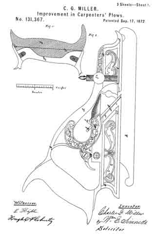
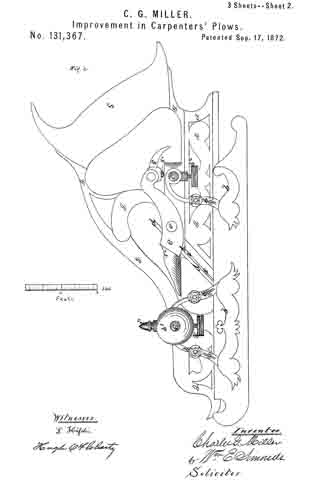
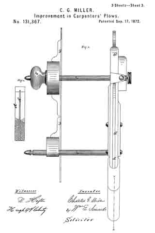
Figure 1 is a side elevation of that side in which the cutting-“iron” is held. Fig. 2 is a side elevation from the opposite side. Fig. 3 is a plan view. Fig. 4 is a view of the under side of the cutting-“iron” Fig. 5 is a central vertical section ofthe handle through the dotted line x x.
The letter a indicates the main body of the plow, cast of metal, in one piece, with ornamental designs thereupon ; b, the guide at the left side of the plow, also cast in one piece. The letters c c’ indicate rods, which are screwed into the side of the main body a, and thereby made detachable therefrom at pleasure, so that the plow can be taken apart and packed into a small compass when not in use. This is believed to be a new feature and an improvement. The guide b slides upon these rods, being set at any desired point by means of the set-screws b1 b2, which are placed underneath the rods, and thus out of the way of the left hand of the operator. The placing of these screws in this position is also believed to be new. A knob, b3, pierced for the introduction of the rod c, projects from the left side of the guide b, thus affording a support for the left hand of the operator. This also is believed to be new. The cutting-chisel d, commonly called the “iron,” is secured in its place when in use by means of the balanced clamp e, embracing the body a, pivoted at e’, and operated by means of the cam f, which has an adjusting-screw, f1, by means of which the clamp can be made to pinch the “iron” with as much or as little force as desired. The application of such a clamp to this purpose and in this manner is believed to be new. To the end of this clamp is attached a shaving-guide, f2, not greatly unlike, in shape, the mold-board of a farmer’s plow, which avails to turn the shavings to the right and away from the plow as the chisel produces them from the wood. This combination of a shaving-guide with the clamp is believed to be new. The “iron” d is roughened on the under surface, at its base end, for the purpose of taking hold upon the seat h, upon which it rests. The iron also has a lengthwise groove, d’, which fits upon the edge a1, and thus keeps the iron from any sidewise motion. The base end of the iron rests upon the seat h, but it does not touch the edge a1 till it comes down where the star is, thus allowing the clamp to spring it firnily down into place, and insuring that the cutting-point of the “iron” shall set firmly upon the edge a1 at its lower end, thus obviating any clatter of the “iron.” This arrangenient and construction is believed to be new. Near the front end of the main body at is a gage to determine the depth of the cut of the “iron,” consisting of the fiat metal foot i, attached to the round pillar i1, set at any desired point by the set-screw i2.
The handle s is fastened to the main body a in a peculiar manner. This handle is of wood, slotted on its under side down to the line s’, the width of the slot being just the thickness of the rib a2, which rib is pierced with holes a3. Before the handle is put on, these holes a3 are filled with saw-dust and glue mixed, or with pieces of wood having glue upon them,and when the handle is put on the glue sets and thus fastens the handle on. This is also believed to be new.
I claim as my invention —
1. The combination of the cast-metal body a, the cast-metal guide b, and the rods c c’
screwed into the body a so as to be detachable, for the purpose set forth.
2. The combination of the cast-metal body a, the rods c c’, and the guide b having the set-screws for the said rods under the rods, substantially as described, and for the purpose set forth.
3. The combination of the main body a, rod c, guide b, and knob b3 attached to the guide and pierced for the entrance of the rod, substantially as described, and for the purpose set forth.
4. The balanced clamp e pivoted to the main body a, and operated by means of the cam f, substantially as described, and for the purpose set forth.
5. In combination with the balanced clamp e, the shaving-guide f2 attached thereto, substantially as described.
6. The combination of the chisel or iron, roughened and grooved as described, with the main body as, having an edge, a1, so formed that the “iron” will only touch the body at two points, viz., the seat h and the lower part of the edge a1, substantially as described, and for the purpose set forth.
7. The construction and method shown for attaching the handle s to the main body.
CHARLES G. MILLER.
Witnesses:
WM. E. SIMONDS,
GEORGE G. SILL.