
| PLEASE NOTE: The images presented on this page are of low resolution and, as a result, will not print out very well. If you wish to have higher resolution files then you may purchase them for only $2.95 per patent by using the "Buy Now" button below. All purchases are via PayPal. These files have all been cleaned up and digitally enhanced and are therefore suitable for printing, publication or framing. Each zip package contains all the images below (some packages may contain more), and purchased files can be downloaded immediately. |
UNITED STATES PATENT OFFICE.
_________________
T. A. CHANDLER, OF ROCKFORD, ILLINOIS.
JOINER’S BEVELING-PLANE.
_________________
Specification of Letters Patent No. 19,620, dated March 16, 1858.
_________________
To all whom it may concern:
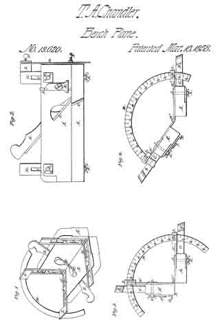
Be it known that I, T. A. CHANDLER, of Rockford, in the county of Winnebago and State of Illinois, have invented a new and Improved Bevel-Fillister and Rabbet-Plane Combined; and I do hereby declare that the following is a full and exact description thereof, reference being had to the accompanying drawings, in which —
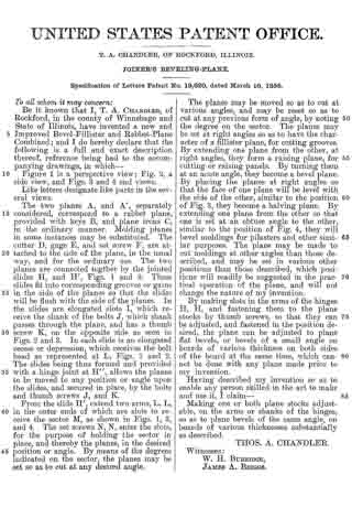
Figure 1 is a perspective view; Fig. 2, a side view, and Figs. 3 and A end views. Like letters designate like parts in the several views.
The two planes A, and A’, separately considered, correspond to a rabbet plane, provided with keys B, and plane irons C, in the ordinary manner. Molding planes in some instances may be substituted. The cutter D, gage E, and set screw F, are attached to the side of the plane, in the usual way, and for the ordinary use. The two planes are connected together by the jointed slides H, and H’, Figs. 1 and 2. These slides fit into corresponding grooves or gains in the side of the planes so that the slides will be flush with the side of the planes. In the slides are elongated slots I, which receive the shank of the bolts J, which shank passes through the plane, and has a thumb screw K, on the opposite side as seen in Figs. 2 and 3. In each slide is an elongated recess or depression, which receives the bolt head as represented at L, Figs. 1 and 2. The slides being thus formed and provided with a hinge joint at H”, allows the planes to be moved to any position or angle upon the slides, and secured in place, by the bolts and thumb screws J, and K.
From the slide H”, extend two arms, L, L, in the outer ends of which are slots to receive the sector M, as shown in Figs. 1, 3, and 4. The set screws N, N, enter the slots, for the purpose of holding the sector in place, and thereby the planes, in the desired position or angle. By means of the degrees indicated on the sector, the planes may be set so as to cut at any desired angle.
The planes may be moved so as to cut at various angles, and may be reset so as to cut at any previous form of angle, by noting the degree on the sector. The planes may be set at right angles so as to have the character of a fillister plane, for cutting grooves. By extending one plane from the other, at right angles, they form a raising plane, for cutting or raising panels. By turning them at an acute angle, they become a bevel plane. By placing the planes at right angles so that the face of one plane will be level with the side of the other, similar to the position of Fig. 3, they become a halving plane. By extending one plane from the other so that one is set at an obtuse angle to the other, similar to the position of Fig. 4, they will bevel moldings for pilasters and other similar purposes. The plane may be made to cut moldings at other angles than those described, and may be set in various other positions than those described, which positions will readily be suggested in the practical operation of the plane, and will not change the nature of my invention.
By making slots in the arms of the hinges H, H, and fastening them to the plane stocks by thumb screws, so that they can be adjusted, and fastened in the position desired, the plane can be adjusted to plane flat bevels, or bevels of a small angle on boards of various thickness on both sides of the board at the same time, which cannot be done with any plane made prior to my invention.
Having described my invention so as to enable any person skilled in the art to make and use it, I claim —
Making one or both plane stocks adjustable, on the arms or shanks of the hinges, so as to plane bevels of the same angle, on boards of various thicknesses substantially as described.
THOS. A. CHANDLER.
Witnesses:
W. H. BURRIDGE,
JAMES A. BRIGGS.