| PLEASE NOTE: The images presented on this page are of low resolution and, as a result, will not print out very well. If you wish to have higher resolution files then you may purchase them for only $2.95 per patent by using the "Buy Now" button below. All purchases are via PayPal. These files have all been cleaned up and digitally enhanced and are therefore suitable for printing, publication or framing. Each zip package contains all the images below (some packages may contain more), and purchased files can be downloaded immediately. |
UNITED STATES PATENT OFFICE.
_________________
F. KILLBRITH, OF PEMBROKE, MASSACHUSETTS.
SHOEMAKER’S EDGE-PLANE.
_________________
Specification of Letters Patent No. 20,882, dated July 13, 1858.
_________________
To all whom it may concern:
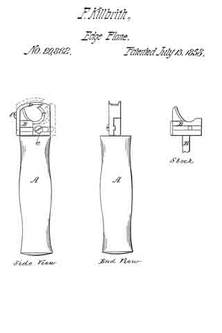
Be it known that I, FREEMAN KILLBRITH, of Pembroke, in the county of Plymouth and State of Massachusetts, have invented a new and useful Improvement on an Implement or Tool called the “Edge-Plane,” Used for the Pairing or Trimming the Edges of Boots and Shoes; and I do hereby declare the following is a full and exact description of said tool, reference being had to the accompanying drawings and to the letters of reference marked thereon.
The nature of my invention consists in attaching to the shank of the edge plane a movable guard which by means of a screw and slide can be moved toward the edge of the knife as the knife wears away by use, so that the space between the edge of the knife and the guard can be regulated at pleasure; and also in making the knife itself movable so that it can be set at any desired gage, and also be removed from the shank entirely to be ground or sharpened.
To enable others to make and use my invention I proceed to describe its construction and operation, reference being had to the accompanying drawings.
A is a common wooden tool handle in which is inserted solid in the end, the iron shank B to which is attached the guard C and the knife D.
C is a movable guard fastened to the shank B by the screw e and which can be moved from right to left as desired and held in its place by the screw e or wholly removed from the shank B.
D is the knife fastened to the shank B by I the screw f which works in a slot in the knife, so that it can be raised or lowered and set to any required gage or by unscrewing entirely be removed from the shank to be ground or sharpened.
To operate this tool with this improvement, when the edge of the knife is worn away by use, by loosening the screw e, the guard C can be moved to the left to the edge of the knife D and by tightening the screw e set at any required distance from the edge of the knife D.
To set the knife to any gage for paring a sole the screw f is loosened and the knife raised or lowered to the desired gage and the screw fastened.
To remove the knife from the shank, remove the screw f wholly.
What I claim as my invention and desire to secure by Letters Patent is —
The attachment to the edge plane now in use and known as Dunham’s patent, of the movable guard C with its screw e, the guard being movable to and from the edge of the knife D, and sliding on the face of the shank, B; and also the attachment to the shank B of the knife D with its screw f working in a slot, and raised or lowered to any desired gage for paring soles, and which knife D can be wholly removed from the shank B by unscrewing the screw f, and so ground or sharpened, and be replaced by a new knife if necessary.
FREEMAN KILLBRITH. [L. S.]
Attest:
JOSEPH COBB,
B. STREETER.


