| PLEASE NOTE: The images presented on this page are of low resolution and, as a result, will not print out very well. If you wish to have higher resolution files then you may purchase them for only $2.95 per patent by using the "Buy Now" button below. All purchases are via PayPal. These files have all been cleaned up and digitally enhanced and are therefore suitable for printing, publication or framing. Each zip package contains all the images below (some packages may contain more), and purchased files can be downloaded immediately. |
UNITED STATES PATENT OFFICE.
_________________
REINHARD T. TORKELSON, OF WORCESTER, MASSACHUSETTS,
ASSIGNOR TO IVER JOHNSON, OF SAME PLACE.
CARPENTER’S PLANE.
_________________
SPECIFICATION forming part of Letters Patent No. 406,605, dated July 9, 1889.
Application filed November 23, 1888. Serial No. 291,675. (No model.)
_________________
To all whom it may concern:
Be it known that I, REINHARD T. TORKELSON, a citizen of the United States, and a resident of the city and county of Worcester, State of Massachusetts, have invented certain new and useful Improvements in Carpenters’ Planes; and I do hereby declare that the following is a full, clear, and exact description thereof, reference being had to the accompanying drawings, forming a part of this specification, and in which —
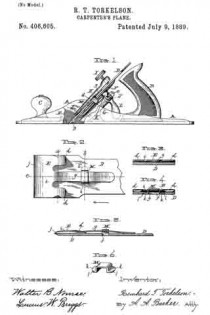
Figure 1 represents a side view, partly in section, of a bench-plane embodying my improvements. Fig. 2 is a plan of the lower part of the cutter with my improved cap secured thereon, as hereinafter more fully described. Figs. 3 and 4 are transverse sections through said cutter and cap, taken on lines a and b in Fig. 2, respectively, looking in the direction of the arrow in said figure. Fig. 5 is a central longitudinal section through the cutter and cap, taken on line c, Fig. 2; and Fig. 6 is a perspective view of the detachable angle-plate employed for adjustably fastening the cap to the cutter, as hereinafter specified.
To enable those skilled in the art to which my invention appertains to better understand the nature and purpose thereof, I will now proceed to describe it more in detail.
My said invention relates to improvements upon the carpenter’s plane patented by O. R. Chaplin in the United States under date of May 7, 1872, No. 126,519; and it consists of improvements in the construction of the cutter and cap, as hereinafter set forth.
In the drawings, the part A represents the plane-stock; B, its handle; C, its knob for holding the front end of the plane; D, the cutter; E, the cap; F, the supporting-saddle, fastened at its lower end to the boss G, projecting up and backfrom the bottom of the stock.
H is the clamp, having the lugs d upon each side adapted to catch under the sides of the saddle.
I is the thumb-screw for operating said clamp.
J is a screw-cam fitted to turn on the stationary pin e.
K is a half-nut projecting down from the upper end of the saddle and engaging with said screw-cam, and L is a lever for operating through the screw-cam and half-nut the saddle and cutter longitudinally.
Any further description of the old parts of the plane may be obtained, if desired, by reference to the patent previously alluded to.
My improvements in the cutter and cap are as follows: Instead of fastening the cap E to the clamp H, as in said Chaplin patent, it is in this instance fastened to the cutter D by forming a transverse opening f in said cutter to receive a transverse angle-plate M, which is passed up through the cutter from the under side, so as to form a holding-loop above the cutter. Through said loop is passed the longitudinal tongue or blade g, formed on the cap E, whereby said cap is held in position. The tongue or blade is made curving or bow-shaped lengthwise, so as to produce a constant pressure upward against the holding angle-plate when it is slipped under the same, and the cap is also provided with two flanges h h, one at each side of the tongue or blade, curved downward, and bearing at their ends upon the top surface of the cutter, the purpose of the latter being to hold the edge j of the cap elevated above the cutter to prevent injury to the cutting-edge of said cutter in the operation of placing the cap in position thereon. Although said flanges h h are preferable for the above purpose, I do not limit myself thereto, as the same result may be obtained by forming the cap so as to bear upon the cutter in a similar manner at any suitable point between the sides or edges thereof, said modification consisting simply in changing the positions of said bearing-points. The same will be readily understood without special illustration in the drawings. The angle-plate is held in position in the cutter against the upward pressure produced by the spring tongue or blade g by means of ears or projections k k, formed upon each end thereof, adapted to bear upon and hold against the under side of the cutter. Said ears are preferably recessed into said cutter, as is shown in Fig. 4, so as to bring the bottoms of said plate and cutter flush with each other. It is also preferable to make the edges of the ears slightly beveled or inclined and the ends of the opening in the cutter correspondingly beveled, as is indicated at l l in Figs. 4 and 6, for the purpose of holding the angle-plate in the cutter after having been sprung into position therein when the cap is not fitted thereto. In practice only a slight bevel is required to effect the desired result. Consequently the plate may be easily sprung into position, as aforesaid. As so slight a bevel would not be perceptible in illustrating the same, I have shown quite a sharp bevel in the drawings, and considerably greater than would be employed in practice.
In fitting the cap to the cutter the angle-plate is first passed up through the opening in said cutter and forced into position, after which said cap is placed on the cutter and its spring tongue or blade g slipped up through the loop formed by the angle-plate projecting above the surface of the cutter. The cap is then adjusted accurately, as required, to govern the thickness of the shaving to be cut, when the cutter, with the cap thus adjusted and secured thereon, is placed in the plane and clamped in position, as in the Chaplin and other planes, by means of the clamp H and its thumb-screw.
Although my invention is more particularly designed to be used in the manufacture of planes whose stock is made of metal, it is equally applicable to other kinds of planes. By thus securing the cap to the cutter, as hereinbefore described, it will at once be manifest to those skilled in the art to which my invention appertains that said cap, being susceptible of adjustment to the cutter before fitting said cutter in position, renders said operation more easy to perform, and also admits of a more accurate adjustment than when said adjustment is made after the cutter has been placed in position. A construction whereby said result may be accomplished is the main purpose of this invention.
If desired, a holding-loop may be formed upon or secured to the cutter to take the place of the detachable angle-plate M. The construction described, however, is preferable.
What I claim as new, and desire to secure by Letters Patent, is —
1. A combined cutter and cap for carpenters’ planes, comprising, in combination, the cutter having a suitable transverse holding-loop above its top surface and the cap having a longitudinal spring tongue or blade adapted to be passed through said loop to hold the cap in position during and after adjustment upon the cutter preparatory to the application thereof to the plane, substantially as and for the purpose set forth.
2. The combination of the cutter D with the detachable angle-plate M, fitted transversely in a suitable opening therein, and the cap E, having the longitudinal spring tongue or blade g, adapted to be passed through the loop formed by said angle-plate when fitted in position in the cutter, substantially as and for the purpose set forth.
3. The combination of the cutter D with the detachable angle-plate M, fitted transversely in a suitable opening therein, and the cap E, having the supporting side flanges h hand the longitudinal spring tongue or blade g, the latter adapted to be passed through the loop formed by said angle-plate when iitted in position in the cutter, substantially as and for the purpose set forth.
4. In a bench-plane, the combination, with the cutter D, having a transverse opening with beveled sides, of the detachable angle-plate M, having flanges with the edges thereof beveled to correspond with the sides of the opening in the cutter, substantially as and for the purpose set forth.
5. In a bench-plane, the combination, with the cutter D, having a transverse opening with beveled sides, of the detachable angle-plate M, having flanges with the edges thereof beveled ito correspond with the sides of the opening in the cutter and the tongue or blade of cap E, substantially as and for the purpose set forth.
6. The combination of the stock, saddle, and clamp device of a bench-plane with the cutter D, provided with a transverse loop above its top surface, and the cap E, having the supporting-flanges h h, and the tongue or blade g, the latter adapted to be passed through said loop to hold the cap upon the cutter during and after adjustment preparatory to the application thereof to the plane, substantially as and for the purpose set forth.
REINHARD T. TORKELSON.
Witnesses:
A. A. BARKER,
W. B. NOURSE.


