| PLEASE NOTE: The images presented on this page are of low resolution and, as a result, will not print out very well. If you wish to have higher resolution files then you may purchase them for only $2.95 per patent by using the "Buy Now" button below. All purchases are via PayPal. These files have all been cleaned up and digitally enhanced and are therefore suitable for printing, publication or framing. Each zip package contains all the images below (some packages may contain more), and purchased files can be downloaded immediately. |
UNITED STATES PATENT OFFICE.
_________________
JEROME E. GREENE, OF TOCCOA, GEORGIA, ASSIGNOR
OF ONE-THIRD TO JOHN McJUNKIN, OF SAME PLACE.
BENCH-PLANE.
_________________
SPECIFICATION forming part of Letters Patent No. 439,061, dated October 21, 1890.
Application filed November 30, 1889. Serial No. 332,142. (No model.)
_________________
To all whom it may concern:
Be it known that I, JEROME E. GREENE, a resident of Toccoa, in the county of Habersham and State of Georgia, have invented certain new and useful Improvements in Roller Bench-Planes; and I do hereby declare the following to be a full, clear, and exact description of the invention, such as will enable others skilled in the art to which it pertains to make and use the same.
The object of my invention is to improve the efficiency of bench-planes and to provide simple and durable devices for adjusting and holding the bit, that can be quickly and conveniently operated; and it consists in the matters hereinafter described and pointed out.
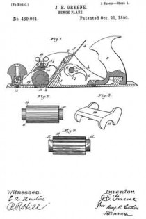
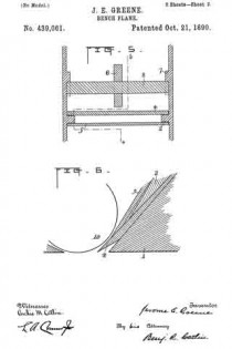
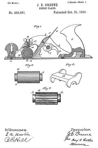
In the accompanying drawings, Figure 1 is a vertical longitudinal section on line a b. Fig. 2 is a side elevation of a roller, and Fig. 3 is a perspective view of a detail. Fig. 4 is a side elevation of a corrugated roller. Fig. 5 is a partial section on line c d of Fig. 1, and Fig. 6 is a partial longitudinal section near one side of the plane.
The body of the plane is preferably made of metal having the side and bottom cast in one piece.
A cross-piece 1, situated just behind the location for the bit, may be cast with the other parts, and also two wedge-shaped pieces 2, one on each side. A handle, which may be secured to the body in any convenient manner, is denoted by 3.
In the present instance the handle is provided in its lower end with an undercut recess, which engages a suitable lug on the plane-body and is then fastened in such position by a screw, as indicated in Fig. 1. A bit is indicated by 4. It is placed on the inclined front side of the support 1 and beneath the side parts 2. The latter at their lower extremities are reduced to a thin edge and receive above them a cap or plate 5, which is conveniently secured to the parts 2 by screws. The part 1 strengthens the plane-body. It also supports the bit at its lower part in a horizontal direction, the slipping of the bit in an approximately vertical direction being prevented by a locking or clamping device which forces the bit against suitable bearings. The spring 5 is made sufficiently strong to force the lower end of the bit upon said support 1.
The bit is locked in any desired position by means of an eccentric 6, journaled in any suitable manner, as by securing-bones 7, having bearings for a rod, bar, or pin 8 to the sides of the plane-body. These bearings are open on the side toward the bit, as indicated in in Fig. 1, and permit the rod 8 with the cam to be inserted or removed when desired by suitably turning them and taking out the bit, if necessary. A handle 9 affords means for suitably moving the eccentric, the bit being released by raising the handle, and gripped or locked by lowering it.
The cap 5 can be made of spring metal, and being prolonged beyond the bearings 2 and bent down upon the bit, as shown, will produce a spring-pressure upon the same. To relieve this tension, the spring-plate is released by loosening its retaining-screws.
As illustrated in Fig. 1, the cap is in close contact with its supports 2 throughout the entire length of the latter. It is obvious that if the cap is of suitable curved form and the compression applied by means of the screws is just sumcient to bend it down upon supports 2 they will appear as represented in Fig. 1.
In Fig. 6 an enlarged view is shown, indicating a small space between the cap and support, which could not be well indicated in Fig. 1. The cap at its lower end has a knife-edge, it being essential that it have a closely-fitted bearing on the bit. By the described construction the fastening together of a bit and its cap in manner heretofore practiced is avoided and the bit can be independently removed or inserted in the plane, and the adjustment of the bit to the cap requires no special attention, for the reason that the cap is permanently fixed in its proper position and the proper adjustment of the bit with reference to the bottom of the plane necessarily secures a suitable adjustment with respect to the cap.
In front of the bit is arranged a roller 10, which is preferably corrugated and is provided with circumferential shoulders 11, forming recesses adapting it to receive springs and be supported thereby. These springs are secured to the body of the plane — one near each side — in any convenient manner, as by screws 13, and a block or saddle 14, having bearings 15, rests upon the reduced ends of the roller immediately above the springs, and the roller is thus sustained between the springs and the bearing-blocks. It can be adjusted vertically to the extent of the resiliency of the springs by means of the screw 16, working through a cross-bar 17 secured in the side of the plane. By running the screw 16 up or down the vertical position of the roller is varied and also its distance from the bit. The bit can in this manner be set according to the nature of the wood or material upon which it is used and the kind of work to be done.
I am aware that rollers have been used in connection with plane-bits, and also devices for adjusting the bit and clamping it from the rear side thereof, and I do not broadly claim such features. I have, however, simplified prior constructions and added to the efficiency of the tool. It will be noted that parts 1 and 2 are cast solid with the body of the plane, and that the spring-plate bears upon the bit at both ends against the action of a simple cam, which latter is so arranged and supported that it is held in its bearings by the bit and can readily be inserted or removed by removing said bit. The structure is quite simple and the parts easily assembled and regulated, and the bit is held very securely. The roller, supported on horizontal springs in or very close to the lower face of the plane, is adapted to bear on the object being planed. The grooves or recesses forming shoulders at the ends of the rollers receive these springs, which lie in a horizontal direction just above the bottom of the plane. The bearing-block 14 rests in the same recesses and embraces the reduced ends of the roller in manner to prevent lateral displacement holding the roller adjustable against the action of the springs.
Having thus described my invention, what I desire to secure by Letters Patent is —
1. In a bench-plane, the combination of the transverse part 1, having a rearwardly-inclined front, the wedge-shaped side parts 2, said parts 1 and 2 being cast solid with the body of the plane, with the bit and the eccentric having journals supported in boxes 7, fixed to the sides of the plane, adapted to press the bit against the bottom of the side pieces, substantially as set forth.
2. In a bench-plane, the combination ofthe transverse part 1, having the inclined front, the wedge-shaped side pieces 2, the bit, the cap fixed upon said side pieces and pressing upon the bit at both its ends, and the eccentric having journals supported in boxes 7, fixed to the sides of the plane, with a handle adapted to press the bit against the bottom of the side pieces and against the cap, substantially as set forth.
3. In a bench-plane, the combination of the bit with a roller, springs secured in the bottom of the plane for supporting the said roller near the edge of the bit, and means for pressing the roller upon its spring-supports, substantially as set forth.
4. In a bench-plane, the combination of the bit, the recessed roller, springs extending into the recesses to support the roller, bearing-blocks resting in said recesses upon the upper side of said roller, and an adjusting-screw for varying the pressure of the bearing-blocks upon the roller, substantially as set forth.
In testimony whereof I have signed this specification in the presence of two subscribing witnesses.
JEROME E. GREENE.
Witnesses:
JOHN McJUNKIN,
E. P. SIMPSON.

