
| PLEASE NOTE: The images presented on this page are of low resolution and, as a result, will not print out very well. If you wish to have higher resolution files then you may purchase them for only $2.95 per patent by using the "Buy Now" button below. All purchases are via PayPal. These files have all been cleaned up and digitally enhanced and are therefore suitable for printing, publication or framing. Each zip package contains all the images below (some packages may contain more), and purchased files can be downloaded immediately. |

United States Patent Office.
E. M. CHAPIN AND SOLON RUST, OF PINE MEADOW, CONNECTICUT.
Letters Patent No. 76,051, dated March 31, 1868.
_________________
IMPROVEMENT IN CARPENTERS’ PLANES.
_________________
The Schedule referred to in these Letters Patent and making part of the same.
_________________
TO ALL WHOM IT MAY CONCERN:
Be it known that we, E. M. CHAPIN and SOLON RUST, of Pine Meadow, in the county of Litchfield, and State of Connecticut, have invented a new and useful Improvement in Ploughs and other Fence-Tools for Joiners’ Use; and we do hereby declare that the following is a full, clear, and exact description thereof, which will enable those skilled in the art to make and use the same, reference being had to the accompanying drawings, forming part of this specification.
The object of this invention is to construct a joiners’ plough and other similar tools, which are provided with adjustable fences, in such a manner that the fence-guides and screws will not extend through the body or stock of the implement, as is now the case, and which is a source of a great deal of annoyance in using such tools, rendering it necessary for the workman, each time the tool is used, to remove out of the way, or to one side, tools and implements of various kinds on the work-bench, which may chance to be at the right-hand side of the tool and near the same.
The invention has further for its object the connecting of the adjusting-screw to the stock of the implement in such a manner that said screw, in case of being broken or injured in any way, may be detached with the greatest facility, and a new screw inserted.
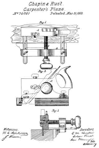
Figure 1 is a plan or top view of our invention.
Figure 2, a side view of the same, partly in section.
Figure 3, a transverse section of the same, taken in the line x x, fig. 1.
Similar letters of reference indicate corresponding parts.
A represents the body or stock of the implement, which may be constructed in the usual way, and B is the fence, which may also be of ordinary construction.
C C are two metallic guides, which are firmly secured, by screws or otherwise, to the face or sole of the stock A, one near each end of the same, said guides being parallel with each other, and provided each with a longitudinal slot, at, extending nearly their whole length. These guides pass through mortises in the fence, the latter being allowed to slide freely on them, and secured at any desired point on the guides by set-screws b b, which pass vertically through the fence into nuts therein below the guides, and press collars c upon the same, as shown clearly in fig. 2. The guides C C project from the left-hand side of the stock A of the plough, and do not extend to the right-hand side of the same.
D is a screw, which passes through the upper part of the fence B, about in line with its centre, and works in an internal thread therein. The inner end of this screw, which is of wood, is turned down to form a tenon, d, which is fitted in the side of the stock A, and allowed to turn freely therein. In the opposite side of the stock A there is made an opening, rather larger in diameter than the opening which receives the tenon d of the screw, but concentric with it, (see fig. 3,) and in this larger opening there is fitted a cylindrical wooden head, e, which has a hole made longitudinally in its inner end, to receive the teuon d, the tenon being secured in e by glue or by a screw.
By this arrangement the screw D has two bearings, f, g, one, f, the shoulder, formed by the tenon clwhich bears against the side of the stock A, and the other, g, the inner end of the head e, which bears against the inner end of the opening in which said head is iitted, as shown clearly in fig. 3.
The fence B is adjusted by turning the screw D, as will be readily seen; and in the event of the breaking of the screw, or the same being injured in any way, it may be cut off adjoining the stock A, and the tenon d driven out of the stock.
The present plan is to have a groove cut circumferentially in the screw, and a key inserted in the stock, so as to pass down into the groove. This plan involves the necessity of withdrawing the key in order to liberate the screw, in case the latter becomes broken or injured. This is attended with considerable diiiiculty, and the stock is invariably more or less disfigured by the operation.
The guides and screw are at one side of the stock only, not projecting through the stock at all, and hence are not in the way of articles on the right hand of the stock, as is the ease with the ordinary ploughs and other adjustable fence-tools, and which involves the necessity of moving articles on the work-bench out of the way of the screws and guides, each time the implement is used.
We claim as new, and desire to secure by Letters Patent —
The joiners’ plough, constructed as described, and consisting of the stock A, having slotted, flanged guides C projecting from one side, the fence B, screw D, formed with a, tenon, d, and fitted with at head, c, and the thumb-screws c’ b, provided with collars c, all arranged and operating in the manner and for the purpose set forth.
E. M. CHAPIN,
SOLON RUST.
Witnesses :
B. G. LOOMIS,
GEORGE W. CHAPIN.