
| PLEASE NOTE: The images presented on this page are of low resolution and, as a result, will not print out very well. If you wish to have higher resolution files then you may purchase them for only $2.95 per patent by using the "Buy Now" button below. All purchases are via PayPal. These files have all been cleaned up and digitally enhanced and are therefore suitable for printing, publication or framing. Each zip package contains all the images below (some packages may contain more), and purchased files can be downloaded immediately. |

UNITED STATES PATENT OFFICE.
_________________
ALEXANDER KALLA, OF NEW YORK, N. Y.
CARPENTER’S PLANE.
_________________
816,335. Specification of Letters Patent. Patented March 27, 1906.
Application filed April 25, 1905. Serial No. 257,299.
_________________
To all whom it may concern:
Be it known that I, ALEXANDER KALLA, a resident of New York city, Manhattan borough, county and State of New York, have invented certain new and useful Improvements in Carpenters’ Planes , of which the following is a specification.
One of the objects of the invention is to provide a combination-plane with improved means for adjusting the cutting-tool.
A further object is to provide improved means whereby a plane-stock or smoothing-plane, for instance, can be attached to a relatively larger stock or shoe, whereby a jack-plane is produced, and to permit of said plane-stock or smoothing-plane to be utilized independently of said larger stock or shoe.
To these and other ends, which will hereinafter appear, my invention comprises the novel features of improvement and combination and arrangement of parts hereinafter set forth, and finally pointed out in the appended claims.
Reference is to be had to the accompanying drawings, forming part of this specification, wherein —
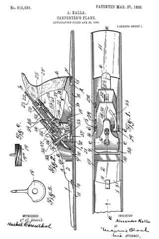
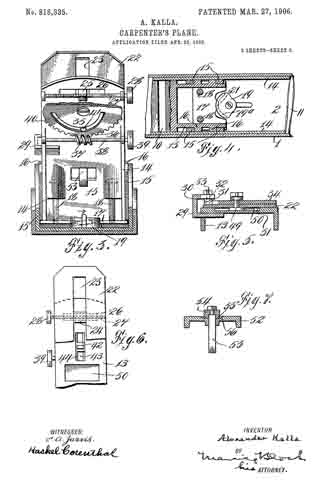
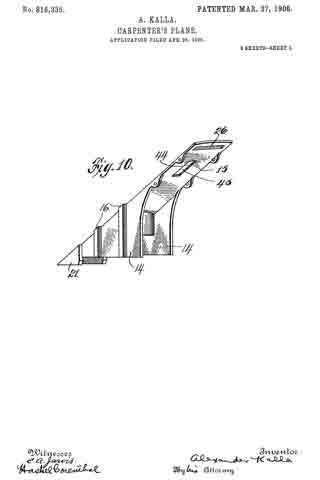
Figure 1 illustrates my improved plane in plan view, one end being broken away. Fig. 2 is a longitudinal section thereof, the section being taken on a line a a in Fig. 1. Fig. 3 is a cross-section thereof, the section being taken on a line b b in Fig. 2 and looking in the direction of the arrow. Fig. 4 is a fragmentary sectional plan view, the section being taken on a line c c in Fig. 2. Fig. 5 is a cross-sectional view of the bit-iron, the section being taken on a line d d in Fig. 1, showing the bit, the clamp for holding said bit, the shave-iron, and means for holding the bit and shave-iron together. Fig. 6 is a fragmentary face view of the bit-iron, showing the means for adjusting the bit longitudinally, the bit being removed, showing also a portion of the shave-iron, and means for adjusting same. Fig. 7 is a cross-section of the clamp-iron, the section being taken on a line e e in Fig. 1. Fig. 8 is a detail plan view of the cam for clamping the plane-stock and shoe together. Fig. 9 is an end view thereof and shows the angular slot therein, and Fig. 10 is a perspective view of the bit-iron.
Like characters of reference indicate corresponding parts in the several views.
Referring to the accompanying drawings, special reference being made to Fig. 2, the numeral 1 indicates a shoe which has supported thereupon a smaller plane 2, the stock 3 of which is held in place by a forward dog 4 and a rear dog 5. As will be seen, the dog 5 is adapted to pass into the opening A in the bottom of the handle 6 and catch upon a projection 7, which in this instance is a portion of the bottom 8 of the stock 3. An opening 9 is formed in the bottom 8 of the stock 3, which alines with an opening 10 in the bottom 11 of the shoe 1, and, as is obvious, the said two openings are for the purpose of permitting an entrance of the bit of the plane 2. The back end of the opening 10 is tapered, as at 12, for a purpose to be hereinafter explained. The bit-iron 13 of the plane 2 is movably mounted thereupon, and to permit of a vertical movement, at the same time precluding displacement, I mount upon the sides 14 of the plane guides 15, Fig. 4, and upon the bit-iron 13 slides 16. As will be seen, the arrangement of said guides and slides is adapted to prevent any tendency toward movement excepting in a vertical plane. Upon the bottom of the bit-iron 13 I secure a plate 17, which is held against said bottom by screw-bolts 13 13, Fig. 3. Said plate 17 is carried beyond the sides 14 of the shoe to an extent which permits the said plate to contact the guides 15. This has for an object to line up the bit of the plane 2 with the bottom of said plane when detached and used independently of the shoe, as without such provision the bit-iron could be raised to any extent and alinement of the bit would be difficult.
Upon the bottom 8 of the plane 2 I mount a segment 19. Within the periphery of the rounded portion of said segment is cut a groove 19a, said groove being angularly disposed with reference to the axis of the pin 20. (See Figs. 3 and 9.) Within said groove a tongue 21 upon the plate 17 is adapted to fit. The bottom surface of the nose 21′ of the bit-iron 13 is designed to come flush with the bottom of the bottom portion 11 of the shoe 1 when said shoe and plane 2 are locked together for use, the rear edge of said nose being slightly tapered to correspond with the tapered edge 12 of the bottom 11 of the shoe 1. The locking process will now be explained. When the plane 2 is detached from the shoe 1, the bit-iron 13 will of course be raised to its highest position, that being when the plate 17 is in contact with the guides 15. To raise and retain the bit-iron in this position, it is but necessary to operate the segment 19 , as per the arrow, Fig. 3, or, in other words, to operate it so that the angular groove 19a forces the plate 17 upwardly and jams it in place against the guides 15, which act as an abutment. Supposing it to be in this position and I wish to place the plane upon and lock it to the shoe 1, I place it upon the dogs, as shown by dotted lines B, Fig. 2, the opening A in the bottom of the handle 6 being large enough to do this. Having done this, the nose 21′ of the bit-iron 13 will be substantially over the opening 10 in the bottom 11 of the shoe 1. By reversing the segment 19 or pushing it opposite to the direction of the arrow in Fig. 3 the whole bit-iron will be forced downwardly, sliding in the guides 15. The tapered rear edge of the nose 21′ will contact the tapered edge 12, and further movement will tend to jam the plane 2 against the dogs. It will of course be understood that the tapered edges referred to will be designed to allow the bottom of the nose 21′ to aline with the bottom 11 of the shoe 1 substantially at the same time that the said jamming of the plane 2 occurs.
Upon the bit-iron 13 I mount the usual bit 22, special means for adjustment being employed. Within the bit 22 I place a lonitudinal slot 23, which may be as long as disirable, and within this slot a block 24, Figs. 2 and 6, is fitted, said block having a projection 25, Figs. 2 and 3, which passes through a transverse slot 26 in the bit-iron 13, Fig. 3, said projection being adapted to work therein. A threaded spindle 27 is rotatably mounted upon said bit-iron and passes through a threaded hole within the projection 25 of the block 24, a thumb-wheel 28 being provided for operation. The function of the block 24 is obvious — namely, to adjust the bit 22 transversely of the bit-iron 13, or, in other words, to enable the operator to bring the cutting edge of the bit in proper relationship with the work. When properly adjusted, the bit 22 is held in place or secured against movement by the clamp 29, Fig. 5, said clamp being provided with a cam 30, which coacts with an opposite cam 31, which is carried by a pin 32, rotatably supported by said clamp 29, a lever 33, Fig. 1, carried by said pin 32, being the means for operation. The clamp 29 is loosely mounted upon the bit-iron 13 and may be moved outwardly, thereby bringing the cams away from the bit in the event of a desire to disassemble. Upon said bit 22 I mount the usual shave-iron 34, Figs. 1 and 2, with special means for adjustment, said means being a wheel 35, carried by the bit-iron 13, said wheel being provided with teeth 36 upon a portion of its periphery, a worm 37, carried by a rotatable shaft 38, supported upon the bit-iron 13, being the means for rotating the wheel 35, a thumb-wheel 39 being provided for the purpose of rotating the shaft 38. Within the wheel 35 I provide an eccentric slot 40, into which a projection 41 of a block 42 projects, Figs. 2 and 3. The block 42 works in an opening 43, Fig. 6, in the bit-iron 13, said opening being provided with guides 44 and said block 42 with guideways 45, Fig. 2. The block 42 carries a nib 46, Fig. 1 , which enters an opening to fit it in the shave-iron 34. By rotatin the wheel 35 by the means described the block 42 can be moved up or down in the opening 43, thereby moving the shave-iron toward or away from the work. To clamp the shave-iron in position, a clamp composed of a cam 46′ , carried by said shave-iron, Figs. 2 and 5, and a cam 47, carried by a lever 48, is provided. The lever 48 carries a rotatable spindle 49, which is provided with a block 50, which is within a recess 51 in the bit-iron 13 and under the bit 22. When the lever 48 is rotated properly, the cams 46′ and 47 by means of the spindle 49 force the bit and bit-iron together, thereby clamping same, the bit being held, as has been explained, by the clamp 29.
To prevent chattering, I provide a clamp-iron or wedge 52, Figs. 1 and 2, said clamp-iron bein provided with a hook 53, which is movabfy mounted therein, the means for operation being a swivel-cam 54, Fig. 7. The points 55 of said cam 54 will rest within a recess 56, formed within the iron 52, when the members are not clamped, and when it is desired to clamp the members together the said points 55 will ride up are inclined sides of said recess 56 when the cam is rotated. This will draw the nose 57, Fig. 2, of the hook 58 up against the bit-iron 13, thereby clamping the shave-iron and bit as a whole against the bit-iron. A spring 58 is provided and is so adjusted as to tend to constantly force the hook 53 backward, this being for the purpose of facilitating the disassemblage of the clamp-iron from the bit-iron. At the back end of the clamp-iron 52 a pin 59 is provided to limit the downward movement of the back end of said iron, suitable openings being provided in the bit and shave-iron for the hook to ass through, as shown.
It will be obvious from the foregoing that the plane 2 can be disengaged from the shoe 1 and used as a smoothing-plane, and it will also be evident that many of the minor details of construction may be varied without departing from the spirit of my invention.
Having now descriibed my invention, what I claim, and desire to secure by Letters Patent, is —
1. An improved carpenter’s plane comprising a stock, an adjustable bit-iron carried by said stock, said bit-iron being provided with a bit and shave-iron, means for adjusting said bit and shave-iron with reference to each other, an opening in the bottom of said stock, a projecting nose upon said bit-iron adapted to pass through said opening, and means for imparting a vertical movement to said bit-iron, whereby the bit thereupon can be adjusted relatively to the bottom surface of said stock.
2. An improved carpenter’s plane comprising a stock, an adjustable bit-iron carried by said stock, said bit-iron being provided with a bit and shave-iron, means for adjusting said bit and shave-iron with reference to each other, an opening in the bottom of said stock, a projecting nose upon said bit-iron adapted to pass through said opening, a cam carried by said stock, means carried by said bit-iron for engaging said cam, and means for operating said cam in such a manner as to impart a vertical movement to said bit-iron whereby the bit thereupon can be adjusted relatively to the bottom of said stock.
3. An improved carpenter’s plane comprising a stock, an adjustable bit-iron carried by said stock, said bit-iron being provlded with a bit and shave-iron, means for adjusting said bit and shave-iron with reference to each other, an opening in the bottom of said stock, a projecting nose upon said bit-iron, said nose having the rear wall thereofin contact with the bottom member of said stock, whereby chattering of the bit is prevented, a cam carried by said stock, means carried by said bit-iron for engaging said cam, and means for operating said cam in such a manner as to impart a vertical movement to said bit-iron whereby the bit thereupon can be adjusted relatively to the bottom of said stock.
4. An improved carpenter’s plane comprising a stock, vertical guideways carried by said stock, a bit-iron adjustably mounted in said guideways, a bit and shave-iron adjustably mounted upon said bit-iron, an opening in the bottom of said stock, a projecting nose upon said bit-iron, said nose having the rear wall thereof in contact with the rear wall of said opening, whereby chattering of said bit is prevented, a cam carried by said stock, means carried by said bit-iron for engaging said cam, and means for operating said cam in such a manner as to impart a vertical movement to said bit-iron, whereby the bit thereupon can be adjusted relatively to the bottom of said stock.
ALEXANDER KALLA.
Witnesses:
HASKEL CORENTHAL,
EMANUEL ELLER.